

 Jul 5 2013, 02:32 AM, updated 12y ago
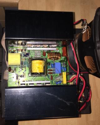
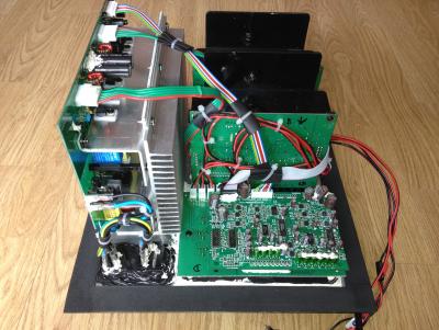
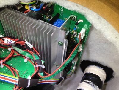
A client brought in a Creative GigaWorks S750 7.1 speaker system for repair. Main problem is the speaker system cannot be powered up at all. Usually many people would assume that it was due the fuse blown whenever their equipment lost all power, however very often that is not the case. The fuse on this speaker system is easily accessible from outside (right under the power socket) and the fuse was found to be OK. Thus the fault is definitely internal (possibly on the power supply board).
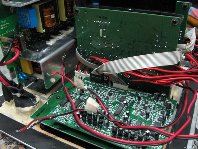
First look inside
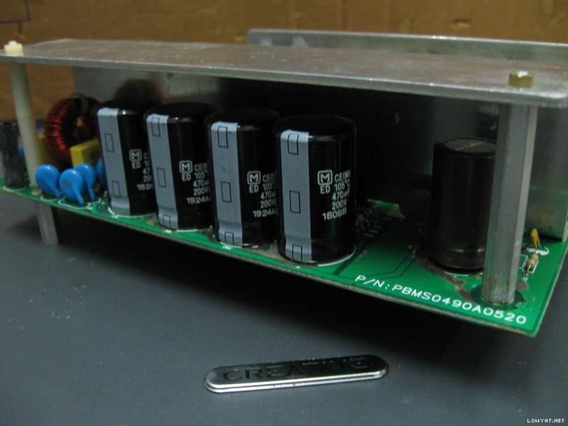
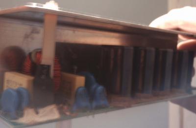
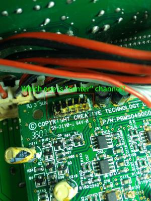
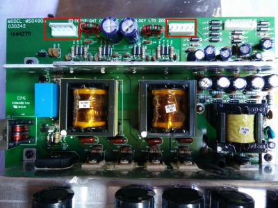
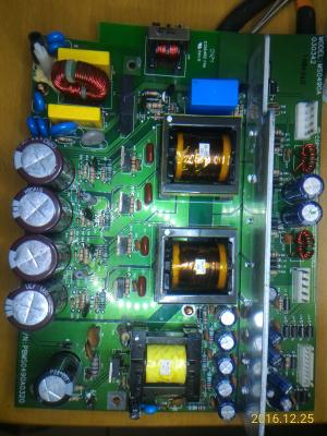
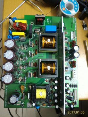
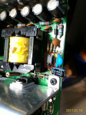
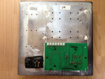
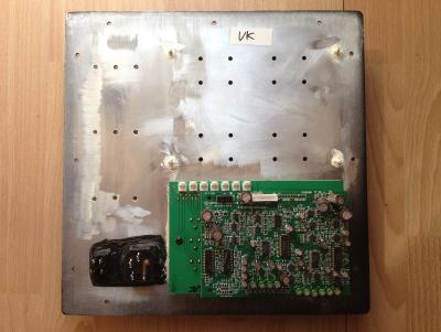
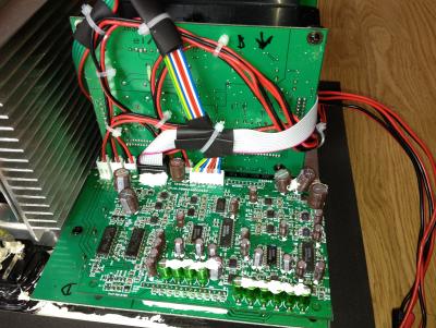
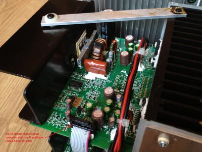
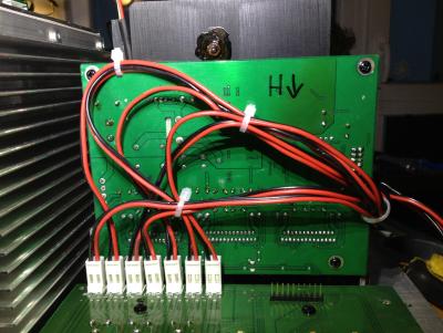
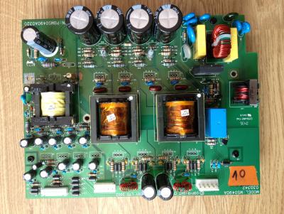
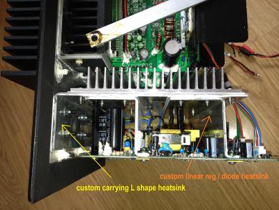
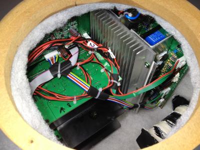
The first thing to do is to look at the power supply board. This speaker system uses SMPS (switched-mode power supply) for all its power requirements. There are two SMPS sections on this board, one for standby power and the other for power amplifiers. As with other Creative GigaWorks series, a relay is used to switch on/off the power to the power amplifier section.

The light blue thingy labeled "Goodsky" is the relay.
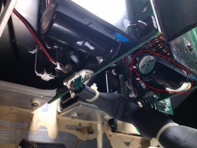
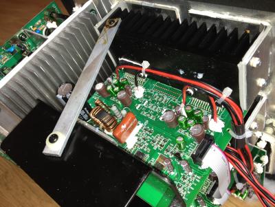
Visible signs of failed components
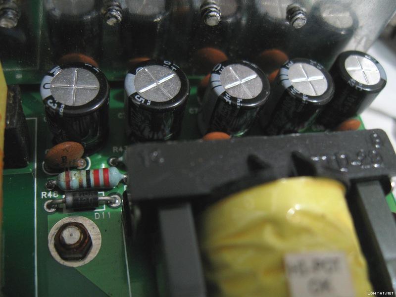
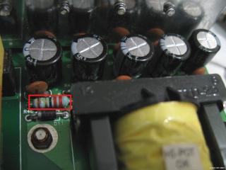
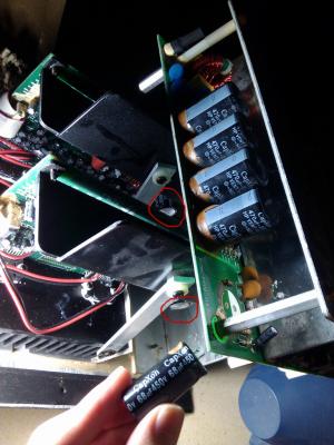
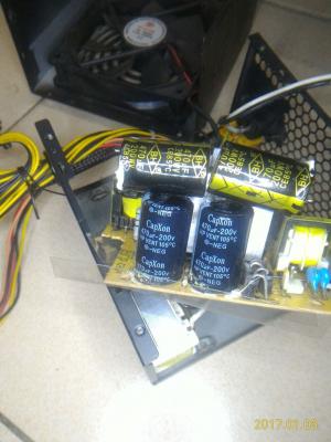
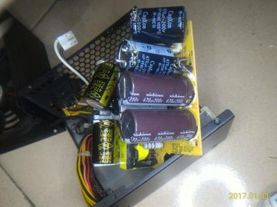
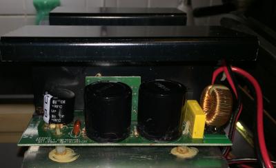
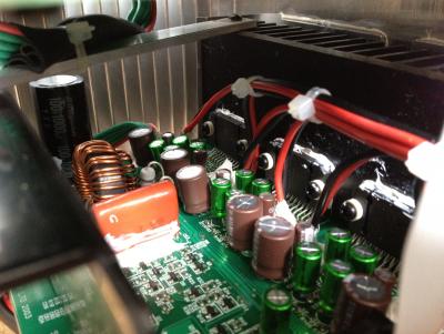
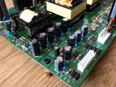
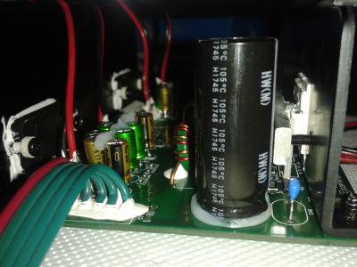
Right away can see those big CapXon HP series capacitors in various stages of bulging, a blown diode and lots of degraded glue (the brown stuff). The design of that heatsink towering over the capacitors would have easily caused to capacitors to bulge due to prolonged heat exposure from the toasty heatsink. Anyway CapXon is not a good capacitor brand at all and is very well known for bad capacitor problems. In fact, its very common to see failed CapXon capacitors in many electronic equipment such as computer PSUs, LCD monitors, AC-to-DC adapters, etc...

Bulging capacitors, blown diode and degraded glue on the primary side.
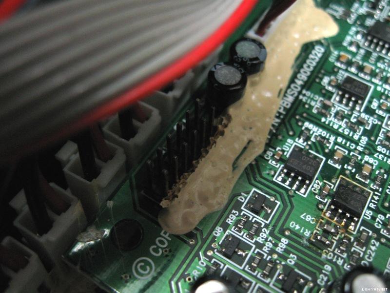
Beware of degraded glue
Thus, why repeatedly the concern on degraded glue? Because degraded glue can become conductive and creates all sorts of weird problems (including short circuits)! You can read more about it here: Conductive Glue Carnage. Thus removal of degraded glue was essential.
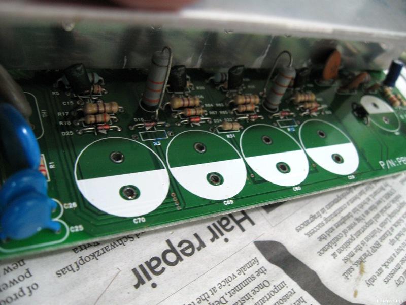
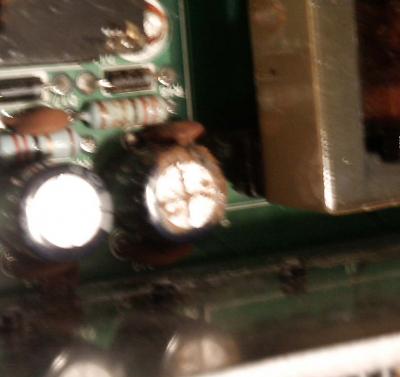
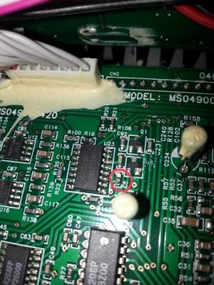
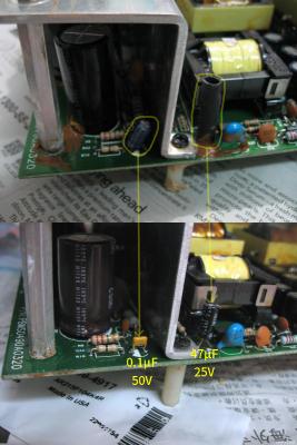
One of the snubber network ceramic capacitors literally cracked and fell apart into pieces when removing more degraded glue...

This is what was left after degraded glue was removed. One of the ceramic capacitor legs can still be seen there.
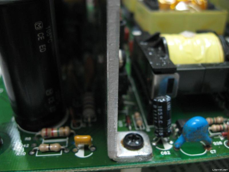
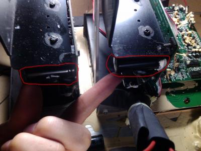
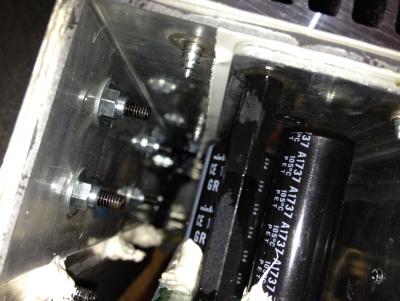
Degraded glue and standoffs plus GND connection equals trouble
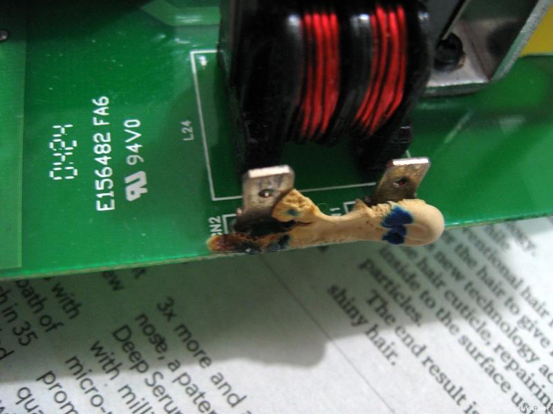
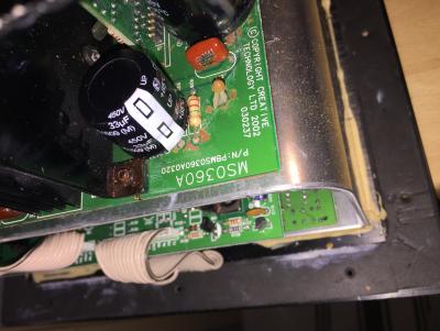
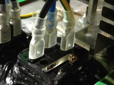
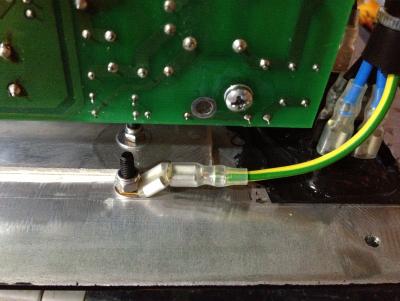
These standoffs are connected to the aluminium heatsink and to GND rail! Thus the degraded glue around other standoffs had to be removed to prevent current and future problems.

Metallic standoff with connection to heatsink and GND!

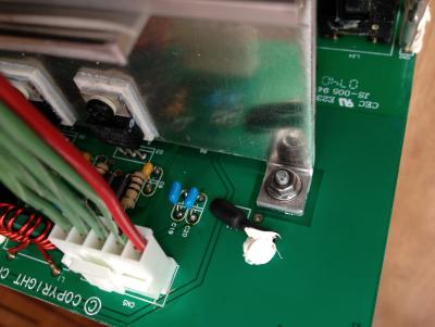
The plastic standoff with degraded glue removed reveals a pad to GND connection also!
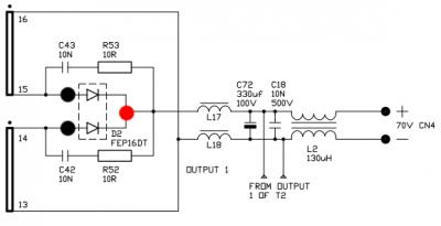
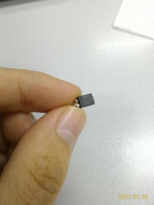
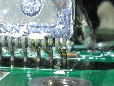
Its also possible that the diode blew due to degraded glue plus that metallic standoff (which is connected to GND!). This is the closeup of the blown diode and the blob of degraded glue that extends all the way to the metallic standoff. This diode is in the primary high voltage section! The diode is blown to beyond recognition (very little left of the markings). Later I did found out the actual part number for this diode from schematics...

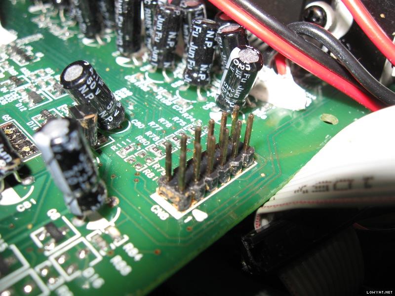
More signs of possible future problems
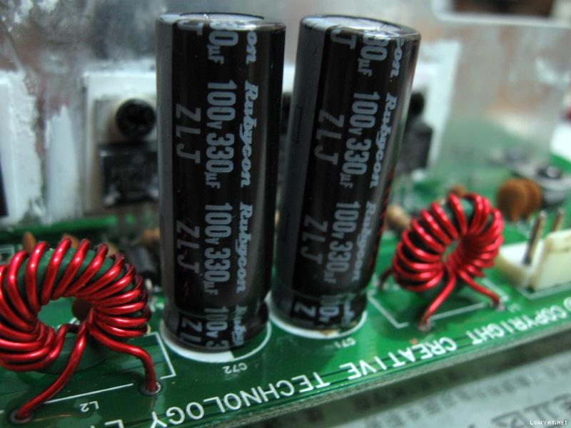
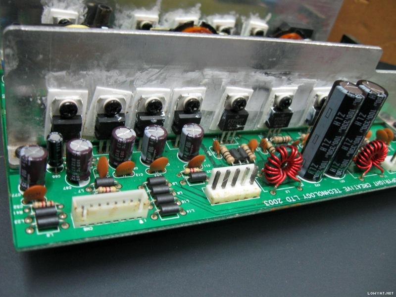
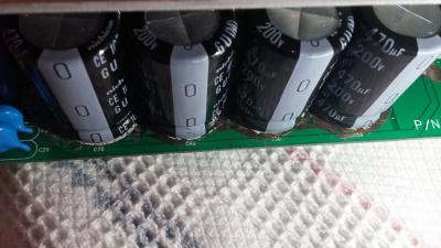
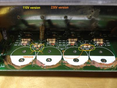
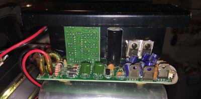
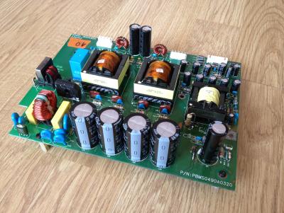
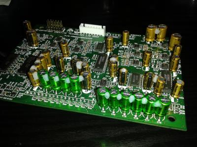
Simply said, more CapXon junk. These capacitors with blue sleeve are all CapXon GS series 85C general purpose type which are not really suited for SMPS (switched-mode power supply) usage. Usually for SMPS, they should be higher temperature 105C low ESR or low impedance type. How did Creative engineers get away with this? Notice those disc-shaped ceramic capacitors besides them? By using ceramic capacitors in parallel to serve/function as the low ESR side! Anyway its quite common to see this configuration in some power supplies (as a method of cost cutting).

Capacitors for the power amplifier side right after the rectifiers...

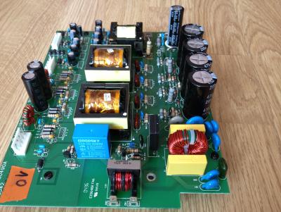
Capacitors for the standby power side right after the rectifiers. The cracked ceramic capacitor and degraded glue were cleaned up as well.

Capacitors for the standby power output side right after the linear voltage regulators.
Besides those CapXon, there were also a Su'scon SL series 85C general purpose capacitor and a S.J.E RH series 105C general purpose capacitor. Thus my recommendation to the client was also to replace/upgrade all those el-cheapo crap capacitors with high quality low ESR and low impedance capacitors suitable for SMPS.
This post has been edited by lex: Aug 12 2013, 09:35 PM
 Quote
Quote


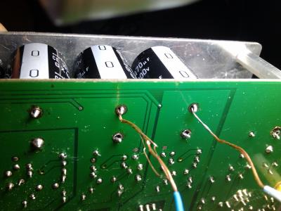
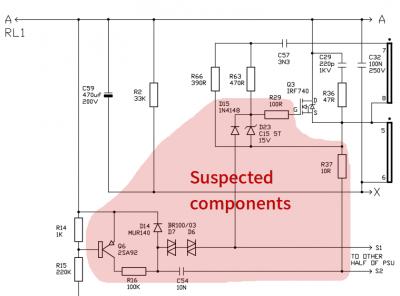
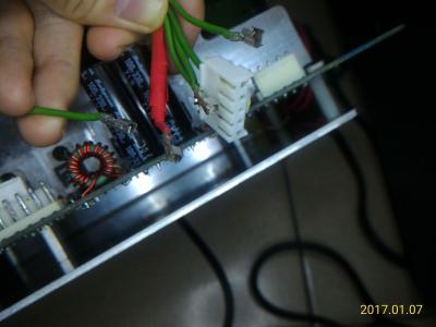
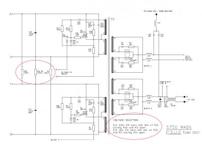
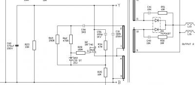
 And I know how to read the connections on PCB now! It had distorted sounds before, I carefully replaced some parts, including blown diodes, one zener, some capsm and one IRF740 connected to blown diodes. Soldering on such PCB especially dealing with damaged pads is a frustrating thing, using L connections through holes, scratching solder mask then create connections, have to be very careful. Anyway, without your help, it couldn't be done, cheers!


 but I can deal with research)
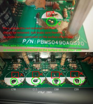
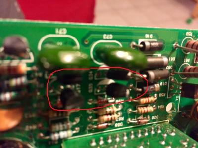
 ). On the amp board I've changed C40 (totally burned out), C39 (sligtly burned by C40), C81 and 91 glued to death...


.jpg)
.jpg)
.jpg)
.jpg)
.jpg)
.jpg)
.jpg)
.jpg)
 Disclaimer
.jpg)
.jpg)
.jpg)
.jpg)
.jpg)
.jpg)
.jpg)
.jpg)
.jpg)


 .
. ", said by
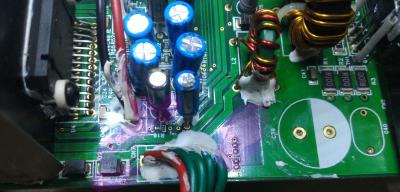


 1.5376sec
 0.65
0.65
 6 queries
 GZIP Disabled