

This post has been edited by Jjk86: May 25 2016, 08:09 AM
Attached thumbnail(s)

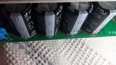


PC Audio Creative GigaWorks S750 7.1 speaker repair, A short guide and info with pictures...
|
|
 May 25 2016, 02:44 AM May 25 2016, 02:44 AM
Return to original view | Post
#1
|

Junior Member
5 posts Joined: May 2016 |
Hello while I was scraping the conducted glue I scraped off the green layer like in the imageσ below. Also the pads are gonners and I made some with your methods... Can you please tell me if I am doing something wrong or if I will have problem without the green layer cause i i tried to turn on the system and i saw a flash. You can see the blown part on the white surface in the 1st image.
This post has been edited by Jjk86: May 25 2016, 08:09 AM Attached thumbnail(s)
|
|
|
|
|
|
May 25 2016, 08:22 PM
Return to original view | Post
#2
|
|
Junior Member
5 posts Joined: May 2016 |
QUOTE(asenrzhang @ May 25 2016, 12:31 PM)  Even as an amateur, I can tell that's totally wrong: you'are connecting '+' to '-' which definitely made a short circuit. That's why you will saw a flash (I made a similar mistake too - I reversed one capacitor). The 'L' connector should only made for the '-' pin of C59 C60 C69 C70 and the '+' pin of C61, because these pins are connected on this side. [attachmentid=6711318] http://img.vim-cn.com/fd/32ef3dc7a80e2ca70...8d21746a3fc.png And the 'L' wire should be better facing the other hole/pin, because the capacitor pin is a little wider which leave spaces inner side. See my wiring below: [attachmentid=6711733] [attachmentid=6711736]  Thank you asenrzhang for your answer  ! !
Unfortunately the back of my pcb doesnt have any pads also how can i connect the capacitors on the back on the down side? Is there a chance my capacitors are blown now due to the short circuit? |
|
|
May 26 2016, 01:09 AM
Return to original view | Post
#3
|
|
Junior Member
5 posts Joined: May 2016 |
QUOTE(asenrzhang @ May 25 2016, 05:59 PM) If you mean the pad around '-' leg of C59 C60 C69 C70 and '+' leg of C61 on the down/back side, then it is not a big issue. If you see carefully on my last photo, the pads are missing too (thanks for my bad soldering skill) I just finished the soldering and modding of the solder pads and my s750 is working again For me, I just put lots solder on it (but DO NOT connect it to the copper surface around), and make a small globe which can make the capacitor more steady. I'm going to put glues on the capacitor to make it more steady. I can't tell. But you may want to check the fuse first. Then check these capacitors using a multimeter. My mistake caused 3-5 fuses blown, but the capacitor survived (Nichicon capacitors seems so damn good). My mistake is I soldered a new capacitor on the left amplifier board - the big one, the 1000μF one, but it's reversed. But after several fuses blown, this capacitor is still working. . Thank you for everything you have been a BIG help! There is only one problem though... My bass is not woriking as it was. It is not making loud bass sound, almost not hearing it at all sometimes and i need to enable the bass boost option on my sound card and when i disable the bass rederection i hear bass sounds from the surround speakers...    This post has been edited by Jjk86: May 26 2016, 01:10 AM |
|
|
May 26 2016, 02:14 AM
Return to original view | Post
#4
|
|
Junior Member
5 posts Joined: May 2016 |
Hmmmm ok i will try this method mate, although i have never touched the woofer and it was working perfectly till the system started doing the blinking green power light. I will dismantle it and i will try to remove this massive glue on the pcb. Thank you again for your help.
This post has been edited by Jjk86: May 26 2016, 02:18 AM |
|
|
May 26 2016, 04:34 AM
Return to original view | Post
#5
|
|
Junior Member
5 posts Joined: May 2016 |
I just cleaned most of the degraded glue on the sound I/0 pcb and checked on the subwoofer for any problems but i found none. The strange is in CMSS-3D option of the sound card program, if i enable it or no i see no difference and if i raise the bass % from 50% to 100% i hear more bass coming from the satellites instead of the subwoofer and the sound is becoming way too bad...
This post has been edited by Jjk86: May 26 2016, 04:40 AM |
| Change to: |  0.0164sec 0.0164sec
 0.49 0.49
 7 queries 7 queries
 GZIP Disabled GZIP Disabled
Time is now: 5th December 2025 - 08:35 AM |
 Quote
Quote