

QUOTE(jojeealmani @ Nov 23 2019, 06:10 PM)
Can you please share email address...i will send you video about what my system is doing

From.where i can get STA575 ics? all.of.them.newPC Audio Creative GigaWorks S750 7.1 speaker repair, A short guide and info with pictures...
|
|
 Nov 27 2019, 01:22 AM Nov 27 2019, 01:22 AM
|

Probation
13 posts Joined: Jul 2019 |
QUOTE(jojeealmani @ Nov 23 2019, 06:10 PM) Can you please share email address...i will send you video about what my system is doing From.where i can get STA575 ics? all.of.them.new |
|
|
|
|
|
Nov 27 2019, 05:24 AM
|
|
Junior Member
104 posts Joined: Feb 2017 |
QUOTE(jojeealmani @ Nov 23 2019, 02:10 PM) Can you please share email address...i will send you video about what my system is doing Upload the video some free site and send me the link, but i can't determine exactly what component is failed just from system behavior. |
|
|
Nov 27 2019, 05:33 AM
|
|
Junior Member
104 posts Joined: Feb 2017 |
QUOTE(jojeealmani @ Nov 26 2019, 06:22 PM) From.where i can get STA575 ics? all.of.them.new I am afraid there this will be very hard to obtain new ones because these are obsolete nowadays. But on ebay there are a lot of. |
|
|
Nov 29 2019, 01:40 AM
|
|
Probation
13 posts Joined: Jul 2019 |
QUOTE(MichalD @ Nov 27 2019, 02:33 AM) I am afraid there this will be very hard to obtain new ones because these are obsolete nowadays. But on ebay there are a lot of. See the below screenshot. bought these online today and hope it works..the second number below STA575 on my ic is a changed. The purchased ic number below sta575 is changed. Also what is zip27 ic?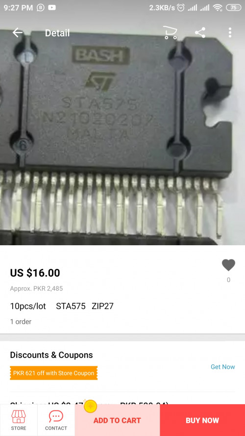 Attached thumbnail(s) 
|
|
|
Nov 29 2019, 05:20 AM
|
|
Junior Member
104 posts Joined: Feb 2017 |
QUOTE(jojeealmani @ Nov 28 2019, 06:40 PM) See the below... The number below changed is no problem. zip27 or flexiwatt27 is the name of the chip package. ic is short for integrated circuit. But i think the problem will not be with the ic itself. The ic chips contains various protections built in. |
|
|
Nov 29 2019, 05:22 AM
|
|
Probation
13 posts Joined: Jul 2019 |
QUOTE(MichalD @ Nov 29 2019, 02:20 AM) The number below changed is no problem. zip27 or flexiwatt27 is the name of the chip package. ic is short for integrated circuit. But i think the problem will not be with the ic itself. The ic chips contains various protections built in. i will made the video and send the link by tomorrow for checking |
|
|
|
|
|
Nov 29 2019, 05:23 AM
|
|
Junior Member
104 posts Joined: Feb 2017 |
QUOTE(jojeealmani @ Nov 28 2019, 10:22 PM) i will made the video and send the link by tomorrow for checking ...OK |
|
|
Nov 30 2019, 05:07 AM
|
|
Probation
33 posts Joined: Nov 2019 |
Hi again, MichalD! Everything is not as good with my power supply as I thought.
It has now been found that the output voltages of voltage stabilization channels 70v are highly dependent on the load current of this channel. The open circuit voltage of both of them is 70 ... 72v. If I load one of the channels with a current of 140ma with the corresponding resistor, the voltage at the output of this channel drops steadily to 57v (while the voltage of the second 70v channel does not change, and all the voltage of the standby power supply stabilizers is normal). I still can not understand how the output voltage is stabilized in the 70v channel circuit. The only feedback circuit that can be seen there is through the additional windings of transformers T1 and T2 (terminals 1, 2 and 7, 8) to the corresponding gates Q3, Q2, Q4 and Q1 - but it is not yet possible to understand in detail how this works, and accordingly I can’t purposefully find the cause of poor stabilization. Perhaps you know how this works, and can you help me? |
|
|
Dec 1 2019, 01:39 AM
|
|
Probation
13 posts Joined: Jul 2019 |
QUOTE(MichalD @ Nov 29 2019, 02:23 AM) ...OK Hello Michalkindly find below the links showing videos of problem. Nothing seems burnt in motherboard and no one understand the problem of this issue in my country  link 1: (shows power supply turning on after disconnecting amplifier from psu) https://youtu.be/6d4pkdqy4T8 link 2: (shows after connecting the amplifier cable the power supply shows abnormal function) https://youtu.be/GFzVzkhC5vs |
|
|
Dec 5 2019, 03:18 AM
|
|
Probation
13 posts Joined: Jul 2019 |
QUOTE(MichalD @ Nov 29 2019, 02:23 AM) ...OK Heloo..u their? |
|
|
Dec 5 2019, 06:29 AM
|
|
Junior Member
104 posts Joined: Feb 2017 |
QUOTE(jojeealmani @ Dec 4 2019, 08:18 PM) Heloo..u their? Hello, yes i am here, sorry for my late reply. It seems your power supply is not working properly for powering the amplifier board, it can't deliver enough power to supply the amplifier board, therefore the green light is flickering. No load voltage must be much more than 70V. Mine is about 90V after replacing 4 big caps and C71 and C72. I can not not check what is the voltage under load but i think it was bout 66 V, but i am not sure, i will do a check during this weekend. Do a visual check of C39 40 41 on amplifier board. But i think the big electrolytic caps on PSU board and AMP boards will be beyond their shelf life.Check all diodes with DMM and the 4 mosfets too. Clean the PSU board. Remove the old glue. |
|
|
Dec 5 2019, 06:33 AM
|
|
Junior Member
104 posts Joined: Feb 2017 |
QUOTE(STREXNIN100 @ Nov 29 2019, 10:07 PM) Hi again, MichalD! Everything is not as good with my power supply as I thought.... Hi..., do you have made some capacitors replacement or not? If not i think there will be big capacitors worned out. Check the diodes D2 3 4 5 with DMM. |
|
|
Dec 6 2019, 12:37 AM
|
|
Probation
2 posts Joined: Nov 2019 |
QUOTE(MichalD @ Nov 17 2019, 10:49 PM) Hi, C41 is SMD capacitor 100nF 100V. If C40 and C41 is blowned you need to replace C39 too. There is a relationship between these. Hello,I have cleaned the area around C41 a little bit and I think I need an expert opinion on this. 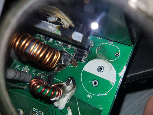 With the explosion of C41 it also took the connection pads for the capacitor + it uncovered a layer beneath the capacitor. 1. Do you think there was a conductive line drawn directly beneath capacitor? (In the middle top to bottom). 2. The right connection pad for C41 was connected to 3 sides? (Top, Right, Bottom) 3. The left conection pad for C41 was connected only to one side? (Top) Thank you Attached thumbnail(s) 
|
|
|
|
|
|
Dec 6 2019, 03:53 AM
|
|
Junior Member
104 posts Joined: Feb 2017 |
QUOTE(Pyros @ Dec 5 2019, 05:37 PM) Hello, Hello, i made a photos for you below:I have cleaned the area around... 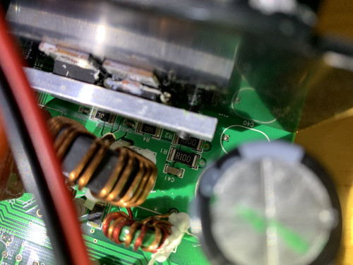 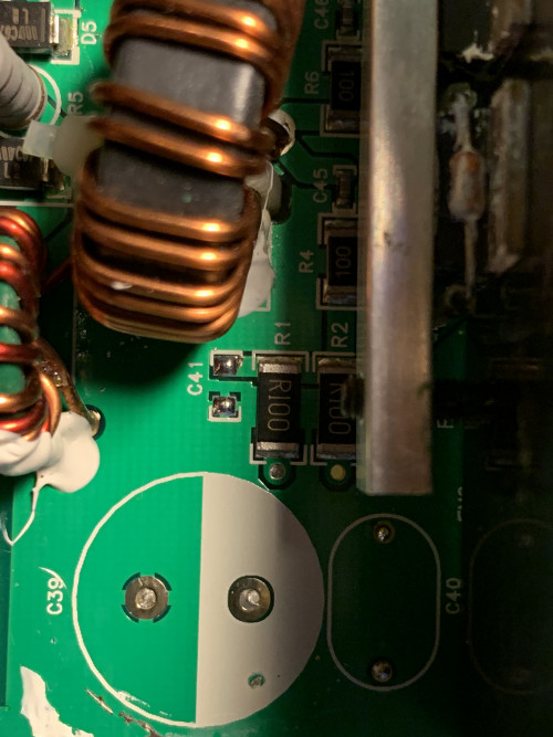 1. Do you think there was a conductive line drawn directly beneath capacitor? (In the middle top to bottom). Yes there was. But no problem if damaged, there are still other sides to make the contact. Just make sure that both pads are not in short circuit. 2. The right connection pad for C41 was connected to 3 sides? (Top, Right, Bottom) No, it was connected to 4 sides as picture shows. 3. The left conection pad for C41 was connected only to one side? (Top) Yes. |
|
|
Dec 6 2019, 05:21 AM
|
|
Probation
33 posts Joined: Nov 2019 |
QUOTE(MichalD @ Dec 5 2019, 01:33 AM) Hi..., do you have made some capacitors replacement or not? If not i think there will be big capacitors worned out. Check the diodes D2 3 4 5 with DMM. Glad to hear from you again!Of course, absolutely all capacitors on the power supply board are replaced with new ones. All at Nichicon. And TOP243Y was replaced - but everything works here, and all the voltages are normal! Diodes D2, 3, 4 and 5, of course, were immediately tested with a good multimeter - they are all working. In addition, I have an oscilloscope, and the waveform on these diodes corresponds to the waveform that should be on good diodes. The whole problem is that I do not understand the principle of stabilizing the output voltage applied here - and not understanding the principle of operation of this non-standard circuit, I can not purposefully find a malfunction in it. I really do not want to engage in a consecutive replacement of all the elements installed on the board at random, in the hope of sooner or later falling into the unusable! In addition, the idea of cross-connecting the outputs of the sections of 70 volt power supplies is not entirely clear to me - but this, it seems to me, is secondary for my malfunction. |
|
|
Dec 6 2019, 05:23 AM
|
|
Probation
33 posts Joined: Nov 2019 |
QUOTE(MichalD @ Dec 5 2019, 01:33 AM) Hi..., do you have made some capacitors replacement or not? If not i think there will be big capacitors worned out. Check the diodes D2 3 4 5 with DMM. Glad to hear from you again!Of course, absolutely all capacitors on the power supply board are replaced with new ones. All at Nichicon. And TOP243Y was replaced - but everything works here, and all the voltages are normal! Diodes D2, 3, 4 and 5, of course, were immediately tested with a good multimeter - they are all working. In addition, I have an oscilloscope, and the waveform on these diodes corresponds to the waveform that should be on good diodes. The whole problem is that I do not understand the principle of stabilizing the output voltage applied here - and not understanding the principle of operation of this non-standard circuit, I can not purposefully find a malfunction in it. I really do not want to engage in a consecutive replacement of all the elements installed on the board at random, in the hope of sooner or later falling into the unusable! In addition, the idea of cross-connecting the outputs of the sections of 70 volt power supplies is not entirely clear to me - but this, it seems to me, is secondary for my malfunction. |
|
|
Dec 12 2019, 11:56 PM
|
|
Probation
33 posts Joined: Nov 2019 |
And yet, if it is possible to measure the open circuit voltage (with the CN4 / CN5 connector disconnected), and under load (with the CN4 / CN5 connector inserted) for any of the channels of the 70 volt power supply. Sincerely. |
|
|
Dec 15 2019, 09:51 PM
|
|
Junior Member
104 posts Joined: Feb 2017 |
QUOTE(STREXNIN100 @ Dec 12 2019, 04:56 PM) And yet, if it is possible... Hello, i've measured the voltages in still working original factory released subwoofer unit.Here are the voltages: 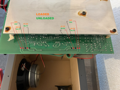 The 86V voltages were slowly raising witout load of amplifier boards. This post has been edited by MichalD: Dec 15 2019, 09:56 PM |
|
|
Dec 16 2019, 02:21 AM
|
|
Probation
13 posts Joined: Jul 2019 |
QUOTE(MichalD @ Nov 29 2019, 02:23 AM) ...OK anyone have a clear photo of below amp board. the repairing guy did something wrong with it. he remove the original parts and damaged the board. if someone have clear photo of it we can check which part is missingAttached thumbnail(s) 
|
|
|
Dec 16 2019, 02:30 AM
|
|
Probation
33 posts Joined: Nov 2019 |
QUOTE(MichalD @ Dec 15 2019, 04:51 PM) Hello, i've measured the voltages in still working original factory released subwoofer unit. Thank MichalD I have without load of amplifier boards 72V, and with a small load of 56V. Now that I have a few times, I'm trying to figure out where the malfunction might be. QUOTE The 86V voltages were slowly raising witout load of amplifier boards. What does "were slowly raising" mean? Does this mean that the voltage really grew slowly (seconds?), or is it just that I misunderstood?It is very important for me to know how a healthy system behaves - I try to understand the principle of its operation from this, and I am very grateful to you for the answers!! A very slow increase in the output voltage (which I don’t have) in your power supply tells me that need to pay attention to the operation of the start-up circuit on D6, D7. ... Or think of something else. ))) (I do not know English very well, so translation may not always be perfect.) |
| Change to: |  0.0319sec 0.0319sec
 1.02 1.02
 6 queries 6 queries
 GZIP Disabled GZIP Disabled
Time is now: 13th December 2025 - 08:36 AM |
 Quote
Quote