Welcome Guest ( Log In | Register )

4 Pages  1 2 3 > » Bottom

Outline · [ Standard ] · Linear+

PC Audio Creative GigaWorks S750 7.1 speaker repair, A short guide and info with pictures...

views
     
asenrzhang
post Apr 18 2015, 06:34 PM

Getting Started
**
Junior Member
68 posts

Joined: Apr 2015
From: China
--content deleted, using another account to post. this account is from a friend--
ok, it seems that another account has problem to post (no one else can see my post except myself), so I post it back here.


Thanks for sharing the repair experience.

» Click to show Spoiler - click again to hide... «

2015-04-23 Update
Damn, I use a flat knife opened the back iron plate, but, I can't open it more, only 5cm: there are wires connected to the subwoofer, I can't see inside how to detach it. Seriously, 5cm, and lots of stuffs blocked the view. I can't even put hand into it.

So how do you guys disassemble it? Can you put your back iron plate down after screw down?

@lex @dlduscg @richer , please help me


2015-04-27 Update
-- Thanks again, now, I had disassembled the the back iron plate, the 3 connectors of the woofer are actually facing inside of the box, so it makes the wire shorter
Attached Image


And 3 bulged capacitors: one CapXon (68μF 450V 105°C), two JunFu (1000μF 100V 105°C, like this one http://forum.lowyat.net/uploads/attach-11/...-1372785951.jpg , @lex does not replace this one because they are not bulged )

Attached Image

Attached Image

Attached Image

This post has been edited by asenrzhang: Apr 27 2015, 07:11 AM
asenrzhang
post May 17 2016, 11:33 PM

Getting Started
**
Junior Member
68 posts

Joined: Apr 2015
From: China
QUOTE(OE DarkThrone @ May 17 2016, 12:32 AM)
Good Day all

I followed the steps in the whole forum to repair and upgrade my S750 surround system but it didn't work sad.gif

my problem wasn't directly with the power board, when my speakers started to die I turned it on one day then I heard sound of something exploding, then the sounds turn lower and the right channel was buzzing
after that day my sound system always turns on but have this buzzing sound problem.

after reading what's written I decided to upgrade the whole components, I checked on the power board, it seems to be OK, no fat Capacitor or burned Diodes or exploded stuff, but I noticed the two Capacitors on the Amp Boards in sector C40 blown and burned.

what I did that I changed most of the parts in the power supply board then some capacitors in the amp boards according to this list (founded earlier in the forum)

https://onedrive.live.com/redir?resid=E2DDC...int=file%2cdocx

- First Repair Results:

power on functioning correct and nothing exploded, but there's no sound at all from any speaker out !!  shocking.gif

- Possible causes:

1 - some soldering points where so fragile, I may have cut/ruined the copper connections down some components on the power board within soldering?
2 - other contact point on the amp board where visibly damaged because of the hot soldering and I tried to fix them, but I got the same results (that didn't encourage me to continue replacing the capacitors in the amp boards)

- Reviewing and Checking for any possible Visible problems:

re-check on every soldering points, cable connections... no visible harm, nothing more to do !!  bangwall.gif

Please Help me find what to do else to complete this mess, I'm so disappointed and exhausted from trying to find the problem with no results regarding that I spent 120 euros to buy the components and feeling useless unlucky.

I can uploads photos for every thing I solder on the boards, please tell me what to do  cry.gif

Thanks
Homer
*
Since currently there's no schematics of amplifier board, maybe you need send to professional to repair.

My self-repair caused a short circuit when power on -- one of capacitor on amplified board was reversed when I soldered it, oops. Luckily, nothing damaged except the fuse. But it took me 1 year to find the problem (yeah, 1 year, leave it on the ground with dust on it until now I decided to repair it again).
asenrzhang
post May 18 2016, 12:57 AM

Getting Started
**
Junior Member
68 posts

Joined: Apr 2015
From: China
Thanks @lex for this amazing helpful post which survived my S750!

I still have some small issues:

1. Center and Subwoofer channel still no sound
My bad, I muted center/subwoofer channel by mistake. I use pulseaudio in Linux operating system, however the center/subwoofer channel is muted in alsamixer:
Attached Image

Anyone know which pin on the audio I/O board is for "center" sound channel?
Attached Image

2. When tune volume + - or mute/unmute or power on to standby, there will be a noise come out of rear speakers (especially rear right speaker). and the volume of noise follows the main volume.

3. There was one time before: after plugged earphone into the jacket on remote control pod, sound still come out from speaker. But now I can't reproduce this issue anymore.

About issue 1 and 2 and 3:
There were massive glues on audio I/O board before, so I scratched them very carefully for several days, but still, there're glues under chips or between chip legs which I can't clean them all. Could this be a reason caused issue 1 & 2 & 3?

Massive glues on audio I/O board
Attached Image

4. The common issue: when power on, power go off automatically and then return to standby state.
-- I'll leave this issue there, since it's not too annoying.


5. Occasionally, there's no sound of the relay after power on button is clicked -- so no power.
The LED light on subwoofer is steady green, after clicked standby/power button, the LEDs on remote control pod are green too, it's seems power is on, but I can't hear the sound of relay.

This post has been edited by asenrzhang: May 23 2016, 09:10 AM
asenrzhang
post May 25 2016, 05:31 PM

Getting Started
**
Junior Member
68 posts

Joined: Apr 2015
From: China
QUOTE(Jjk86 @ May 25 2016, 02:44 AM)
Hello while I was scraping the conducted glue I scraped off the green layer like in the imageσ below.  Also the pads are gonners and I made some with your methods...  Can you please tell me if I am doing something wrong or if I will have problem without the green layer cause i i tried to turn on the system and i saw a flash. You can see the blown part on the white surface in the 1st image.
*
doh.gif
Even as an amateur, I can tell that's totally wrong: you'are connecting '+' to '-' which definitely made a short circuit. That's why you saw a flash (I made a similar mistake too - I reversed one capacitor).

The 'L' connector should only made for the '-' leg/pin/hole of C59 C60 C69 C70 and the '+' leg/pin/hole of C61, because these legs/pins are connected on this side.

Attached Image

user posted image


And the 'L' wire should be better facing the other hole/pin, because the distance between capacitor legs/pins is a little wider which leave spaces inner side. See my wiring below:

Attached Image
Attached Image

This post has been edited by asenrzhang: May 26 2016, 10:21 AM
asenrzhang
post May 25 2016, 10:59 PM

Getting Started
**
Junior Member
68 posts

Joined: Apr 2015
From: China
QUOTE(Jjk86 @ May 25 2016, 08:22 PM)
Unfortunately the back of my pcb doesnt have any pads also how can i connect the capacitors on the back on the down side?
If you mean the pad around '-' leg of C59 C60 C69 C70 and '+' leg of C61 on the down/back side, then it is not a big issue. If you see carefully on my last photo, the pads are missing too (thanks for my bad soldering skill)
For me, I just put lots solder on it (but DO NOT connect it to the copper surface around), and make a small globe which can make the capacitor more steady. I'm going to put glues on the capacitor to make it more steady.

QUOTE(Jjk86 @ May 25 2016, 08:22 PM)
Is there a chance my capacitors are blown now due to the short circuit?
I can't tell. But you may want to check the fuse first. Then check these capacitors using a multimeter.
My mistake caused 3-5 fuses blown, but the capacitor survived (Nichicon capacitors seems so damn good).
My mistake is I soldered a new capacitor on the left amplifier board - the big one, the 1000μF one, but it's reversed. But after several fuses blown, this capacitor is still working. biggrin.gif

This post has been edited by asenrzhang: May 25 2016, 11:18 PM
asenrzhang
post May 26 2016, 01:51 AM

Getting Started
**
Junior Member
68 posts

Joined: Apr 2015
From: China
QUOTE(Jjk86 @ May 26 2016, 01:09 AM)
I just finished the soldering and modding of the solder pads and my s750 is working again biggrin.gif. Thank you for everything you have been a BIG help! There is only one problem though... My bass is not woriking as it was. It is not making loud bass sound, almost not hearing it at all sometimes and i need to enable the bass boost option on my sound card and when i disable the bass rederection i hear bass sounds from the surround speakers... dry.gif  confused.gif  hmm.gif
*
I have similar issue too, but not on the subwoofer / bass channel. It's volume of the Side Left and Side Right and Rear Left channels are a little bit lower.

Do you follow the guide in #7 post of this thread? I actually bought sandpapers to make the pins shining.
Attached Image

Also, I scratched glues on the audio I/O board too. I suspect those massive degraded glues on audio I/O board may caused my issue, but I'm not sure, it's out of my skills. rclxub.gif
user posted image

This post has been edited by asenrzhang: May 26 2016, 02:06 AM
asenrzhang
post May 26 2016, 12:15 PM

Getting Started
**
Junior Member
68 posts

Joined: Apr 2015
From: China
QUOTE(Jjk86 @ May 26 2016, 02:14 AM)
Hmmmm ok i will try this method mate, although i have never touched the woofer and it was working perfectly till the system started doing the blinking green power light. I will dismantle it and i will try to remove this massive glue on the pcb. Thank you again for your help.
*
QUOTE(Jjk86 @ May 26 2016, 04:34 AM)
I just cleaned most of the degraded glue on the sound I/0 pcb and checked on the subwoofer for any problems but i found none. The strange is in CMSS-3D option of the sound card program, if i enable it or no i see no difference and if i raise the bass % from 50% to 100% i hear more bass coming from the satellites instead of the subwoofer and the sound is becoming way too bad...
*
Sorry, my bad. I didn't make it clear, you may not need to check on the woofer speaker. I didn't mean the woofer issue, but only mean "More problems - sound channel randomly goes off" section in #7 post, and the degraded glues on audio I/O board.

To be more clear, I'm talking about make these pins shining as @lex did:

user posted image

user posted image

There're 3 set of these pins, one on audio I/O board, one on power amplifier board 1, one on power amplifier board 2.

This post has been edited by asenrzhang: May 26 2016, 04:41 PM
asenrzhang
post May 26 2016, 01:16 PM

Getting Started
**
Junior Member
68 posts

Joined: Apr 2015
From: China
--delete--

This post has been edited by asenrzhang: May 26 2016, 01:22 PM
asenrzhang
post May 31 2016, 09:42 PM

Getting Started
**
Junior Member
68 posts

Joined: Apr 2015
From: China
QUOTE(asenrzhang @ May 18 2016, 12:57 AM)
...
5. Occasionally, there's no sound of the relay after power on button is clicked -- so no power.
  The LED light on subwoofer is steady green, after clicked standby/power button, the LEDs on remote control pod are green too, it's seems power is on, but I can't hear the sound of relay.
*
Now, it's dead again on issue 5 -- power LED & POD LEDs are ok, but it's just no sound came out. But sound came out from the right channel of earphone if I plug the earphone to POD, the left channel of earphone has very very low sound (nearly quiet, I must increasing the volume to hear it).

This symptom remind me I had same issue after I bought this speaker for just one week, I posted my issue on official creative forum, but no solution.
Here's my post on forums.creative.com 7+ years ago: http://forums.creative.com/showthread.php?t=506230

But this time, since I already fixed power supply board issue (I think so, because the power output to power amplifier board seems ok. Although I don't know how much voltage reading is good, but it's as same as the voltage reading when this speaker been revived), I suspect it's something wrong on power amplifier boards or audio I/O board.

After I powered on for some time (perhaps half an hour), then power off, I touched the heat sinks -- the heat sink on power supply board is warm, but the heat sinks on two amplifier boards are not warm, so how to check which component on power amplifier board caused this issue (no visual damage)?

===============
by the way, the voltage output readings of some connectors:

CODE

CN5 (to power amplifier board 2)
==================================================
.     .     .     .    [.]RED
|<------ 85.5v -------->|
     |<---- 18.7v ---->|
           |<--24.1v-->|
                 |48.7v|
|<---- 36.8v ---->|
|<--61.4v-->|
|66.8v|
==================================================

CN4 (to power amplifier board 1)
 almost as same as CN5

CN6 (to audio I/O board)
==================================================
.     .     .     (0)     .     .     .    [.]RED
|     |     |      |      |     |     |     |
0v   4.3v  8.9v    0    12.2  -7.9v   0    8.9v
==================================================

And the voltage reading between two legs of each 330μF/100V capacitor is 66.6V.


This post has been edited by asenrzhang: Jun 6 2016, 02:07 AM
asenrzhang
post Jun 27 2016, 03:36 PM

Getting Started
**
Junior Member
68 posts

Joined: Apr 2015
From: China
QUOTE(juli3t @ Jun 23 2016, 04:36 AM)
Hi

new guy,  no electronics experience.  Got an S750 that just packed up when I plugged headphones in,  the green power light still blinks,  but the red control unit light won't come on.

  • My own repairing experience told me that could be the problem of C61 capacitor and/or the D9 diode neerby, I mean these two Attached Image .
  • And there's one time that I may made a short circuit between the heatsink of AMP board and it's aluminum support box, it also caused power LED blinking issue.


QUOTE(juli3t @ Jun 23 2016, 04:36 AM)
I actually have another broken unit as well that has no green power light working - I kept it after buying a new one in case I found some one who can repair them.
Any chance I can bought it? tongue.gif My own repairing on PSU board seems ok, but now I have another issue -- there're no sound (actually it's low volume distort sound) on SideLeft & SideRight & Center & Subwoofer channels, these channels are all connected to power amplifier board 2, so I'm thinking to bought another AMP board 2 or a failed set to replace it.

QUOTE(juli3t @ Jun 23 2016, 04:36 AM)
Is there anyone here who can repair it for me - for money - of course?

or does anyone know any good audio electricians who might be able to do it for me? 

Anywhere in the UK,  I think overseas shipping might be too much - but not actually sure.
lex seems received a pack from oversea, he is definitely the right guy you want to sent your speaker to him to repair.
If you prefer local repair service, I think you can try search on internet (I found several S750 repair service provider on taobao -- eBay like website in China)

QUOTE(juli3t @ Jun 23 2016, 04:36 AM)
There's nothing comparable on the market at all at the moment,  and I REALLY like this setup.
True, I'm satisfied with the sound quality of S750, that's why we all want to fix it instead of buy another speaker.

asenrzhang
post Jul 17 2016, 03:12 PM

Getting Started
**
Junior Member
68 posts

Joined: Apr 2015
From: China
excl.gif Disclaimer: I'm not a professional electronic engineer, not even an amateur, so, take the advice at your own risk.

QUOTE(rsseco @ Jul 17 2016, 03:28 AM)
...
As the leds are still on (green on back, red on console), I decided to power on
...
Okay, it seems the standby part of power supply board works ok (C61 is not been made a short circuit or open circuit)

QUOTE(rsseco @ Jul 17 2016, 03:28 AM)
...
I have a short circuit on the C69 and C59 (the 2nd and 4th ones).
...
Your description may already point out where's the issue came from.

Did you check the solder point of C59 C60 C69 C70 legs on both sides carefully before you "decide to remove all the caps and deport them"?
You don't want to connect the solder point with the copper around - that will make a short circuit.

This post has been edited by asenrzhang: Jul 17 2016, 03:14 PM


Attached thumbnail(s)
Attached Image Attached Image
asenrzhang
post Jul 20 2016, 12:43 AM

Getting Started
**
Junior Member
68 posts

Joined: Apr 2015
From: China
excl.gif Disclaimer: I'm not a professional electronic engineer, not even an amateur, so, take the advice at your own risk.

QUOTE(rsseco @ Jul 19 2016, 12:03 AM)
Thanks for your fast response.
Yes, I did check them, but to be sure, I have remove the capacitor once again to verify ; I already "scratched" with my fingernail to clean around the point holes.
Some pictures to show :

...
The solder pads looks ok to me.

QUOTE(rsseco @ Jul 19 2016, 12:03 AM)
Tested on both side, and Xcrossed too (one test pin on top, other on bottom). I always have this short circuit in cap69 and cap59. This short circuit must come from somewhere else, but from where ? Is it possible another component is "broken" ?
I looked again at the power supply unit schematics of Creative S750, my wild guess is Q3 and/or Q4 and/or R2 could been failed (my guess could be totally wrong).
You may check the resistance between S and D leg of Q3 and Q4 first after desolder them. Then check the resistance of R2 resistor.
Attached Image

QUOTE(rsseco @ Jul 19 2016, 12:03 AM)
Last time, I began to check the diodes, some of them were passive (- >+ and + -> -). As I can remember me, a diode is only passive in one way, right ?
Thank you
*
Not all diode types act like that. I'm not familiar with this too, I learned in this thread and know that there're at least 3 types: ZENER & DIAC & typical diodes on PSU board.
Maybe the wikipedia page [English] [Français] can help.

This post has been edited by asenrzhang: Jul 20 2016, 01:34 AM
asenrzhang
post Jul 22 2016, 03:18 AM

Getting Started
**
Junior Member
68 posts

Joined: Apr 2015
From: China
excl.gif Disclaimer: I'm not a professional electronic engineer, not even an amateur, so, take the advice at your own risk.

QUOTE(rsseco @ Jul 21 2016, 11:09 PM)
...
I checked the R2 (nothing has been desoldered yet) : I have a little value (<1K) before it goes to 0kohm. So it could be dead as you guess !
When R2 is not been desoldered, the test result should have same reading value as when you testing C59 and C69 solder pads
user posted image
user posted image

QUOTE(rsseco @ Jul 21 2016, 11:09 PM)
For comparison, I've check the same resistor (R23), and here I'm getting a stable value, but not the 33k as required (my meter tells me 28.9k, but it is not as precise as it could be, as it's a cheap multimeter. Additional question here, what model could I buy which make capacimeter too ? And not so expensive too : ~max 150 USD)
I hope someone professional can help you choose a proper multimeter.

I bough a cheap meter (Chinese page) (¥84, or $13 biggrin.gif) too for repairing my subwoofer, it can be used to test capacitance too, max 2000μF, capable to test the big capacitor on amplifier board which is 1000μF. So far I'm satisfied with it. But professional engineers may not using such multimeter to test capacitors, especially electrolytic capacitors, if electrolytic capacitors are leaking, it will got a higher reading than it's real capacitance (see my post on badcaps.net).


QUOTE(rsseco @ Jul 21 2016, 11:09 PM)
Are the C32 or C33 not to incriminate ? Or T1 or T2 ?!?  confused.gif ?
Could be, but usually not I guess.

QUOTE(rsseco @ Jul 21 2016, 11:09 PM)
I will check the Q3 and Q4 too see first... When you say "check the resistance between S - D", what sort of value must I find ? Must I determine if S -> D is passive and/or D -> S ?
*
Before testing Q3 and Q4, you need to switch the multimeter to 'Diode' position.

I can only tell that it's failed if D(red pin)→S(black pin) is conductive (as your test result before, almost 0 ohm).

I can't tell the normal reading thought, the datasheets [ST] [Vishay] does not tell the resistance when it's state is OFF.
But since it's a diode between S and D, it should act like a diode when it's not failed: S(red)→D(black) should be conductive (several hundreds ohm 0.4V-0.8V bias voltage reading), D(red)→S(black) should not be conductive.

This post has been edited by asenrzhang: Mar 26 2018, 11:54 AM
asenrzhang
post Jul 25 2016, 01:22 AM

Getting Started
**
Junior Member
68 posts

Joined: Apr 2015
From: China
excl.gif Disclaimer: I'm not a professional electronic engineer, not even an amateur, so, take the advice at your own risk.

QUOTE(rsseco @ Jul 24 2016, 07:59 PM)
Hi  ! 
Some news after testing the things.
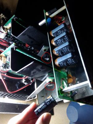
R2 seems to be OK after Q3 and Q4 were removed.
And yes, one of both is NOK, S-D and D-S are conductive, the other one is good (conductive in one way only)
Unfortunately, I can't say which one was defective, as I removed twice before testing each.
Well, it's doesn't matter now, just throw the failed one away biggrin.gif

QUOTE(rsseco @ Jul 24 2016, 07:59 PM)
So, I need to buy at least one IRF740 component (I think I will buy 2 or 4 to replace twice or all  ? ) what do you think  ?
You can buy more components for backup if it doesn't hurt tongue.gif . (Note: If you're buying from internet market, make sure you don't buy extra quantity -- if you bought 1, the seller may send 10, so you only need buy 1 in such case -- the aliexpress page you posted is such an example blush.gif )
When I repairing my subwoofer, I bought a lots extra components, because the delivery fee is more expensive than the components fee bangwall.gif . For example, I bought 100 fuses & 100 1N4004 diodes (for replacing D9) which I only need one of each bangwall.gif

QUOTE(rsseco @ Jul 24 2016, 07:59 PM)
I must thank you once again  !  And hope after replacement, my S750 will work again  !
Hope you don't have other failed components. If it's the only component failed, your subwoofer should work again after replacement.

QUOTE(rsseco @ Jul 24 2016, 07:59 PM)
Edit  :  there's a lot of irf740 on internet. I think they all act the same  ?
Since IRF740 is the model name of this component, different manufactory/company (SGS-Thomson (ST), Vishay, Internationa Rectifier, ON Semiconductor, etc...) can manufacture it, so they should be same.

QUOTE(rsseco @ Jul 24 2016, 07:59 PM)
I have some inscription under the irf740 reference (I R 345F) What does it mean  ?
If 'I R' you mean "I(a diode symbol)R", then it's the logo of International Rectifer company (it's Infineon now: 2015-01-13 Infineon Technologies AG successfully acquires International Rectifier).
I don't know what's '345F' means, maybe it's a product line number, I don't know... rclxub.gif Other marks may used for manufactured date (week of year) or country.


QUOTE(rsseco @ Jul 24 2016, 07:59 PM)
I found a bundle on aliexpress  :  http://fr.aliexpress.com/item/10pcs-free-s...308.0.40.a4K1j5

But I will try to found someones in old electronic stuff I have, perhaps I don't need to buy (the shipment does take too long...)
*
If you have an old working one in same model (IRF740) & same package/case (TO-220-3), that's will be the quickest way to replace it.

If you don't find an old one, maybe you can try local electronic market first, or try buy from a local reseller on internet market, that could save a lot shipping time.

(Note again: if you buy from the aliexpess page above, you only need to buy 1, because it's a 10pcs deal )

This post has been edited by asenrzhang: Jul 29 2016, 12:02 PM
asenrzhang
post Aug 12 2016, 08:43 PM

Getting Started
**
Junior Member
68 posts

Joined: Apr 2015
From: China
QUOTE(rsseco @ Aug 12 2016, 02:57 AM)
Today was THE day !

And finally... it's alive again ! Thank you very much !
Congratulations! I'd like to see every dead S750 subwoofer been revived! rclxms.gif

QUOTE(rsseco @ Aug 12 2016, 02:57 AM)
But, as I remove the 2 mosfets for testing 3 weeks ago, I don't remember where I put the screws with the ceramic spacer to fix these mosfets...
*
Maybe you need a small components box with some grids in it to store these screws, like the following
Attached Image

This post has been edited by asenrzhang: Aug 12 2016, 08:52 PM
asenrzhang
post Aug 12 2016, 08:48 PM

Getting Started
**
Junior Member
68 posts

Joined: Apr 2015
From: China
QUOTE(tezro @ Aug 12 2016, 12:51 PM)
Hi.

Anyone who has old faulty S750 subwoofer for sale?

I would like to buy one to get parts for my faulty S750 subwoofer. cry.gif

Thank you.
*
I found one on eBay a month ago, it's still available now.
http://www.ebay.com/itm/322220223412

I tried to buy it, but since I'm newbie on eBay (zero feedback), the owner cancelled my bidding sad.gif
asenrzhang
post Aug 13 2016, 05:24 PM

Getting Started
**
Junior Member
68 posts

Joined: Apr 2015
From: China
QUOTE(rsseco @ Aug 13 2016, 02:09 AM)
I disassemble an old PSU and remove the screws and spacers from the mosfets inside. So, I mounted my S750 sub this evening. And finally, I said victory too early... powered on, 2s, and shutdown  bye.gif  bye.gif
The fuse blowned again ! I'm disappointed !

So, let's go again to dissamble this shit again  vmad.gif
Sorry to hear that, I guess there're still issues somewhere.

I think you can isolate the issue on power amplifier board first:
  1. Check potential failed components, at least check same component which failed last time. If failed, replace them.
  2. Replace fuse
  3. Unplug CN4 & CN5 connector on power supply board, this will isolate issues on power amplifier board
    Attached Image
  4. Power on again
    • If fuse is still blown, it indicate there're still issues on power supply board.
    • If fuse is not blown, you may check power amplifier board now.

QUOTE(rsseco @ Aug 13 2016, 02:09 AM)
I think I will need your help again in the next days, if you're already ok ?
*
I'd like to help if I can. But I can only diagnose very basic issues.
asenrzhang
post Aug 14 2016, 09:18 PM

Getting Started
**
Junior Member
68 posts

Joined: Apr 2015
From: China
QUOTE(rsseco @ Aug 14 2016, 03:57 AM)
..
One thing which I found strange as I checked all component after I soldered the capacitor, on one (C69 or C60, I don't remember exactly) the negative pole was "shortcuting" the circuit under the board (I check if no solder was touching out the "round", it was OK). On two capacitors, I had to do the trick with some cable in "L"-shape so I could solder on the bottom (as you can see on the picture)

user posted image
*
If your power voltage is 220V~240V, I mean the accepted input voltage of your S750 subwoofer is 220V~240V, according the power supply board schematics, C59- C69- C60+ C70+ should be short circuited.


Attached thumbnail(s)
Attached Image
asenrzhang
post Aug 17 2016, 03:39 AM

Getting Started
**
Junior Member
68 posts

Joined: Apr 2015
From: China
excl.gif Disclaimer: I'm not a professional electronic engineer, not even an amateur, so, take the advice at your own risk.

QUOTE(rsseco @ Aug 16 2016, 11:29 PM)
...
What I found :

- R36, in front of Q3 (replaced by new mosfet) seems to have burn. But not really sure it comes from the resistor, as I've got always 46.7 Ohm (same as R38, in front of Q4). On your doc, it says "47R, so it should be OK). I check (visually) the capacitor in front (C29), on one pin it seems have overheat too (but it's not broken). As I don't have a capacitor-meter, I measure the value in Ohm : I have 530 Ohm, same value as the capacitor in front of R38.

Edit : I check Q3. It seems the "burn" comes from...

- Q4 have split ! (between ceramic and the heatshrink)

see pictures :

My thoughts : are the IRF740 low quality/bad/defective (?), or problem is coming from somewhere else ?.
-> As I tested the old Q3 and Q4 and found only one bad, I can think there can really come from the new ones. (as wrote before, as I removed the two mosfets, I have replaced twice by new ones)

*
Well, when components get burned, it usually means it's overheated or overloaded/over current or over voltage.
  • overloaded/over current: I guess this could be the reason.

    Although the power amplifier boards are not connected, there're still components after transformer, which is a load too, and I guess it could be D2 D3 been failed too, you can check the resistance between 1 and 3 leg of D2 and D3, if the resistance is very low, then the component is failed. Usually it shouldn't be conductive between 1 and 3 leg. See the datasheet: http://pdf1.alldatasheet.com/datasheet-pdf...GE/FEP16DT.html

    Maybe check D4 and D5 too..

  • overheating: I don't think so
  • over voltage: I don't think so

asenrzhang
post Aug 17 2016, 02:39 PM

Getting Started
**
Junior Member
68 posts

Joined: Apr 2015
From: China
excl.gif Disclaimer: I'm not a professional electronic engineer, not even an amateur, so, take the advice at your own risk.

QUOTE(rsseco @ Aug 17 2016, 04:24 AM)
I think I must remove these components before testing, as always  ?
That's the reliable way. But for testing resistance between 1 and 3 leg of D2 D3 D4 D5, you can test without unsolder them, unless something else caused short circuit between 1 and 3 leg (My subwoofer don't have short circuit issue on D2~D5, but I found one piece of degraded glue under one of them, it's between the legs and heat sink, it's hard to be found because I never removed heat sink).

QUOTE(rsseco @ Aug 17 2016, 04:24 AM)
But D2, D3 are in the upper section of the board, is this section not designed for the standby power  ?
I think there're two parts on the upper section, one part is the standby/auxiliary power, another part is main power.
Attached Image
(Photo is stolen from https://forum.lowyat.net/index.php?showtopi...ost&p=69404301)

QUOTE(rsseco @ Aug 17 2016, 04:24 AM)
I re-check the specs of the IRF, they are designed for 400V, so as you say, it's not an over-voltage, as if the power value on this point not exceed this value  ? T1 or T2 could not be the cause  ?
It could be over voltage or T1 T2 's fault, you can check it later.

Standby power and main power come from D1, and your standby part seems works okay, so, keeps your power in standby mode, and measure the DC voltage output of D1. (Just be careful of your safety when measuring, because it has power now)

This post has been edited by asenrzhang: Aug 17 2016, 11:48 PM

4 Pages  1 2 3 > » Top
 

Change to:
| Lo-Fi Version
0.0508sec    0.60    7 queries    GZIP Disabled
Time is now: 6th December 2025 - 04:15 PM