

MichalD.
Attached thumbnail(s)
PC Audio Creative GigaWorks S750 7.1 speaker repair, A short guide and info with pictures...
|
|
 Feb 16 2017, 08:06 PM Feb 16 2017, 08:06 PM
Return to original view | Post
#1
|

Junior Member
104 posts Joined: Feb 2017 |
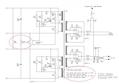
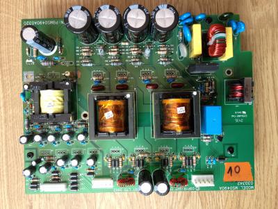
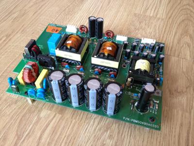
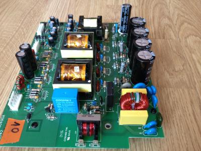
Hello to all, i have sucesfully repaired my S750 set few days ago (both C40 on AMP boards were exploded only, but replaced all big caps and some smaller caps on PSU board even if no one was bulged) (big thanks for this forum and to the people for their helpfull topics), i want to buy another please can somebody tell me what is the difference in the PSU board between US 110V and EU 230V version? In the PSU scheme i found something about R32, R31 and R3. Simply by following these three "resistors" (0 ohm links or open links) can i adapt the PSU board to 230V or 110V input voltages? Thanks for soon reply.
MichalD. Attached thumbnail(s)
|
|
|
|
|
|
Feb 17 2017, 08:50 PM
Return to original view | Post
#2
|
|
Junior Member
104 posts Joined: Feb 2017 |
QUOTE(asenrzhang @ Feb 17 2017, 11:38 AM) I can tell the only different is just different connections of those three 0Ω resistors, as you already found it. Great, thank you for your assurance.With proper modification (the schematics already figure it out), you can make the PSU works on 230V or 110V. 110V to 220~240V modification should be easy, because you don't need to buy another 0Ω resistor. 220~240V to 110V modification is easy too, but you need buy another 0Ω resistor.  |
|
|
Mar 29 2017, 04:11 AM
Return to original view | Post
#3
|
|
Junior Member
104 posts Joined: Feb 2017 |
QUOTE(azuradaniel @ Mar 16 2017, 04:48 AM) Where to send for 110V to 220~240V modification? You can do it yourself, you just need soldering iron, solder, and basic soldering skills. Just look at the pictures. There is "conversion manual" and the other image is 230V version.Attached thumbnail(s) 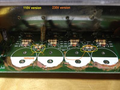

|
|
|
Jun 13 2017, 12:48 AM
Return to original view | Post
#4
|
|
Junior Member
104 posts Joined: Feb 2017 |
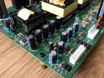
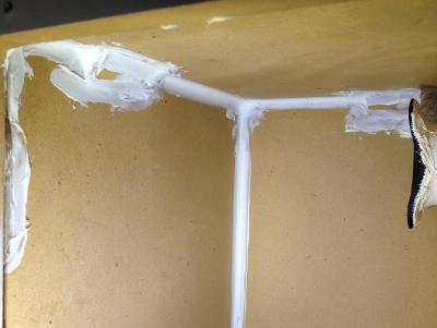
QUOTE(drepou @ Jun 10 2017, 04:14 PM) Hello Every one I am not a profesional electrical enegineer but in basic i can recommend you to do following steps.1. Properly visually check all parts for any kind of damage, crack, pop, burn track from explosion. 2. Measure all FET's and diodes with digital multimeter. http://electronicsbeliever.com/how-to-know...t-is-defective/ 3. Check all caps for capacitance with multimeter capable to measure capacity. Some of them must be desoldered for correct measurements. 4. Check all PCB traces with multimeter in conductivity beep mode. Even check for broken parts leads as i found here: 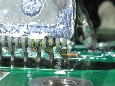
5. Schematics will be very helpful. 6. Check inductors and transformer windings for continuity or resistance. Good luck! |
|
|
Jun 14 2017, 03:32 PM
Return to original view | Post
#5
|
|
Junior Member
104 posts Joined: Feb 2017 |
QUOTE(drepou @ Jun 13 2017, 08:21 PM) i tested all the diode ok work good,... For the S750 PSU board are the thick conductors -24 and +24V and more than 80 V without load (with load-amp boards connected is around 65V)Check the markings for voltage regulators (L or LM7XXX) google it for output voltage and measure input voltage and output voltage directly on the input and output pins. 27V for 7824 is a lot, there must be something close to 24V. 8V is very low to power up the amp. |
|
|
Jun 15 2017, 05:51 AM
Return to original view | Post
#6
|
|
Junior Member
104 posts Joined: Feb 2017 |
QUOTE(drepou @ Jun 14 2017, 05:45 PM) It's was not a good idea... Hmmm, that's weird. In S750 i can connect and disconnet at any time and nothing wrong was happened. Check the diodes again, and power mosfets with diode checking or continuity mode. Does have your circuit TOP243 or similiar? I had one PSU board where was faulty TOP243 and a faulty diode powering it. During this fauilure the PSU board does absolutely nothing, no transformer buzzing, no LED light on, no nothing. After replacing diode and TOP243 everything was working like new even with old capacitors. |
|
|
|
|
|
Jun 16 2017, 03:55 AM
Return to original view | Post
#7
|
|
Junior Member
104 posts Joined: Feb 2017 |
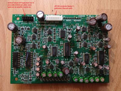
QUOTE(drepou @ Jun 14 2017, 11:43 PM) yes i have a TOP243Y... Chek this PSU scheme for S750 if the TOP243Y part is the same in your PSU and check parts around your TOP243Y specially diodes and find your diode "D9" by following the PCB traces and check it.Attached thumbnail(s) 
|
|
|
Sep 14 2017, 06:34 PM
Return to original view | Post
#8
|
|
Junior Member
104 posts Joined: Feb 2017 |
QUOTE(drepou @ Jul 15 2017, 02:14 PM) hello again i changed the top243 but issue is the same i have only 8,8V on CD+ CD- even if i disconnect the wires going to audio board... Hello, i wasn't here long time because of lot of work and huge fixing for all my other sets of S750. Now i am finishing preparing for much improved heatsink for PSU boards.Without the schematics it is very hard to find the problem. For the resistors i don't know if it is normal. In S750 PSU is grounded only heatsink cooling mosfets. But there is no electrical conductive connection between mosfets and heatsink. The other heatsink for diodes and V.REGs is connected to positive 70V rails thru two capacitors each rail and common inductor. There is no other connection to heatsink so i don't know the purpose of this connection. The other heatsink is connected to positive wave of grid powerline after diode bridge and one D9 if i am right. And now i remember i've touched it with bare hand during operation to check the temperature  Attached thumbnail(s) 
|
|
|
Sep 14 2017, 06:38 PM
Return to original view | Post
#9
|
|
Junior Member
104 posts Joined: Feb 2017 |
QUOTE(smudge827 @ Jul 18 2017, 12:39 PM) Hi, Check the area around the big 1000uF capacitor, small yellow one and SMDs around on both AMP boards. Look for the burned or cracked components. Do you removed all degraded glue from the PSU, AMPs and audio processing boards? By any chance do you know this fault, the Sub light is steady so it is not the same fault again. could this be something stupid like the bass speaker cables come off when I pulled the boards out. I suppose that I could just look, but maybe you know this fault and can help. regards and thanks in advance  smudge |
|
|
Jan 12 2018, 05:09 AM
Return to original view | Post
#10
|
|
Junior Member
104 posts Joined: Feb 2017 |
QUOTE(KrazeyKami @ Jan 5 2018, 01:03 PM) Hi everyone!... Hello, there must be very low resistance path between RL1 A and RL1 B. If the control pod in stanby mode with red LED on the stanby section is probably OK and 400V cap is probably OK too.For 100% sure you can check the D9 with multimeter in diode mode (something 0.4 ~ 0.9V is OK) If you want you can check the voltages on CN6 or skip this section. ----------------------------------------------------------------------------------------------------------------------- 1pos - 2neg...+9V 2neg - 3pos...-8V 4pos - 2neg/5neg...about 12V+ or near 13V 7pos - 8neg about 4.4V 6th pin is +9V for the relay drive, cannot be measeured in your conditions, but if the relay clicked before it is OK. ----------------------------------------------------------------------------------------------------------------------- First check all MOSFETS with multimeter set to diode mode. Can be measured directly on PCB. Source pin positive and drain pin negative. It must shows something about 0,5V. If they are OK, switch to resistace mode and check resistance between gate positive and source negative, if they are OK with near resistors it will show something about 0,94 kOhm because of R29 63 66 etc... If they are OK, check all 4 big caps under the L shape heatsink C59 60 69 70 for resistance or short circuit. There sholud be no continuity or very high resistance. Do this tests and let me know the results. This post has been edited by MichalD: Jan 13 2018, 03:37 PM |
|
|
Mar 14 2018, 05:20 AM
Return to original view | Post
#11
|
|
Junior Member
104 posts Joined: Feb 2017 |
QUOTE(Galeak @ Sep 14 2013, 07:02 PM) I remove glue from the board where there are many capacitors >30 pieces.At power 230V don't hear relay. only from power remote = 2 clicks (power on - power off , very fast). I think it is a circuit remote problem. At next power on from remote, audio sistem works normally. RELAY ISSUE (CONTROL POD RESETING) - SOLVEDSometimes after power on from standby mode with the control pod the relay clicks two times very fast 1st click ON state and 2nd click OFF state (standby). After second power on the relay clicks normally only one time to ON state and the unit is regularly powered on and system is working but the stored settings (volume levels) are reseted. After long time investigating and measuring i've find out that there is no poblem with the relay itself or with the Q5 transistor or even with the control pod. There are 2 types of this issues i've observed. 1.Very fast relay click ON and OFF, about 0,1s between states. I've measured it with osciloscope. +9V between CN6 (1) and (2) supplying the base of Q5 thru R24 and voltage between base and emitter of Q5: 
TOP243Y's voltage between PIN C and S: 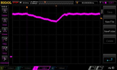
2. Slower relay click ON and OFF, about 0,7s between states. Measeured the same points. 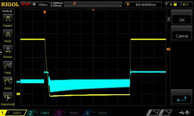
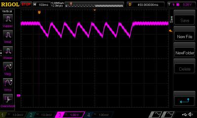
When a fault condition such as an open loop or shorted output prevents the flow of an external current into the CONTROL pin, the capacitor on the CONTROL pin discharges towards 4.8 V. At 4.8 V, auto-restart is activated (this waveform is shown) which turns the output MOSFET off and puts the control circuitry in a low current standby mode. There is a problem with the feedback section of TOP243Y. When this issue occurs, the entire standby power loss section is glitched and this is the reason for resetting the control pod settings caused by power supply loss. I'don't know why this is happening (maybee some interference after power on) but i have reviewed the TOP243Y datasheet and found the working solution for eliminating this issue. 1. I've added 10uF ceramic capacitor to bias winding transformer paralel to C63 (i think the original 0.1uF can be replaced with 10uF but not tested, i've keeped it) Datasheet of TOP243Y recommends 1uF but i've added 10uF. 
2. I've added external bypass 1uF and 0.1uF ceramic capacitor between TOP243Y's PIN C and S as close as possible to supply the instantaneous gate drive current as mentioned in TOP243Y datasheet. 
After this upgrade, I have tested the power supply on and off, hard power off (remove and plug again main power cable) and then power on, all this more than 100 times in a row and all the time every one attempt the power supply powers on, with absolutely NO ONE relay clicking issue. Power suply was working properly. Measured with the oscilloscope and there were no power glitches at all. After upgrade +9V between CN6 (1) and (2) supplying the base of Q5 thru R24 and voltage between base and emitter of Q5: 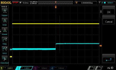
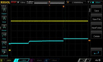
Some two-stage voltage increasing but no error caused. After upgrade TOP243Y's voltage between PIN C and S: 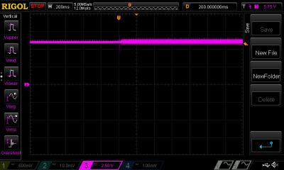
This post has been edited by MichalD: Mar 17 2018, 07:58 PM |
|
|
Mar 18 2018, 11:24 PM
Return to original view | Post
#12
|
|
Junior Member
104 posts Joined: Feb 2017 |
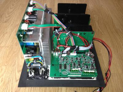
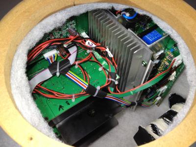
QUOTE(asenrzhang @ Mar 18 2018, 04:36 AM) WOW! 100 times in a row and no 'clicking' issue, that is amazing! Yep By the way, did you glued the capacitors on the other side? I'm worried about they may be affected(loose) by vibration and heat. the TOP243Y's blue caps are X7R and "glued" with transparent PCB lacquer. And now i am not affraid of high temperature, check following:I have made a very comprehensive upgrades and repairs. Backplate: Whole subwoofer backplate with all electronics was dissasembled and the outside heatsing was removed too. Removed and cleaned all degraded glue and backplate was cleaned to aluminium gloss and all glue hard remants was grinded. All pure aluminium heat conductive surface connections was filled with heat conductive paste and the edges was glued to prevent vibrations. Between outside black aluminium heatsink and the backplate was added heat conductive paste too. New edge sealing and bass speaker sealing was applied. 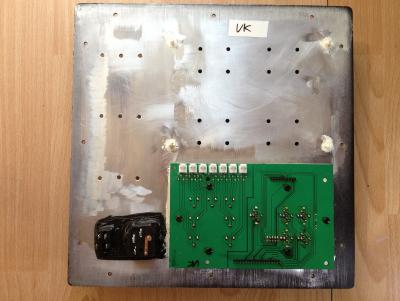


AMP boards, APB board and I/O board: All electrolytic caps on amplifier boards and audio processing board was replaced by ELNA RFS Silmic II and bipolars was replaced by Nichicon MUSE. 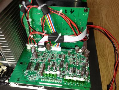


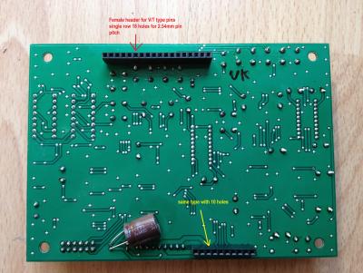
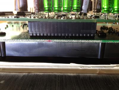
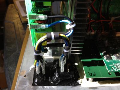
All factory glued connectors and PCB pins was replaced by new ones and all wire contact was crimped with new contact crimps. 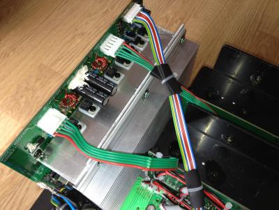
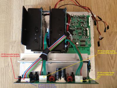


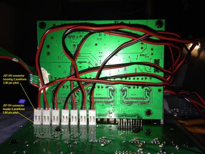
Audio processing board was separated from I/O board and soldered new contact pins and headers to make it detacheable. Input cable was removed and soldered JST-XH 8 pin header and custom cable made for connection to PSU board. New custom made signal cable from audio processing board to amp boards used. Almost all cables was tied together with cable ties. Removed all degraded glue from I/O board and I/O connectors was resoldered with fresh solder. Replaced all JST-VH conn headers. 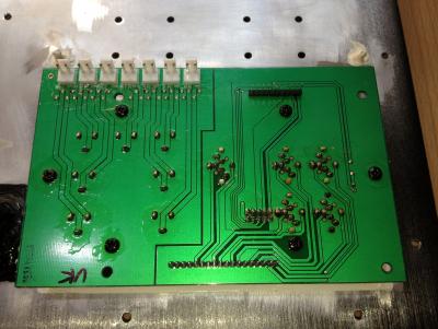


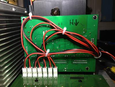
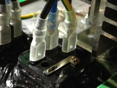
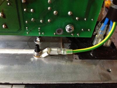
PSU board: Replaced mains power switch and grid input connector with grounding pin connected to backplate with yellow/green wire. 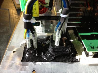


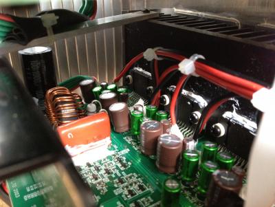
Replaced all electrolytic caps for high quality ones (Nichicon, Rubycon) and the most of ceramic caps. 


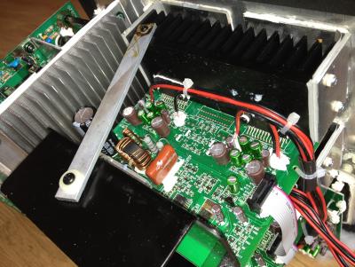
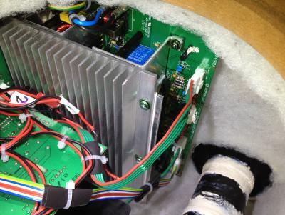
Replaced all TO220's aluminium oxide heat conductive pads (lot of them brokes when disassembled) with heat conductive paste. Custom made linear reg / diode heatsink, shape silmiliar to IRF740 heatsink. Custom made carrying L shape heatsink. Added ribbed heatsink for better heat dissipation. (ebay sourced) 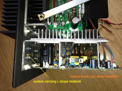
All heat sink connection surface filled with heat conductive pad sheet. All screwed together and screws was glued or transparent protective PCB lacquer lacquered to prevent unscrewing. The most important thing was connect the carrying L shape heatsink to backplate with heat conductive paste for best heat dissipation and tightened using 6 screws with self locking nut and the edges was glued. 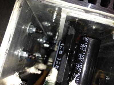

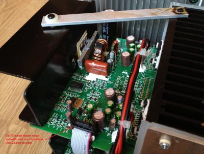
Part of PCB copper pad under heatsink connection near D13 was scraped off to make it unconductive to heatsink. Heatsink side of L11 near C20 was unsoldered and heatshrinked and glued to PCB. 
This makes the heatsink conductive isolated from the power supply board and the mains grounding wire can be safely connected to backplate and now can fulfill its function. 

After this upgrade the heat dissipation is much more better than original which can guarantee much much longer lifespan. In the standby mode the outer heatsink is hand touch cold. In power on and common use the backplate and heat sink after some time are hand touch warm but not hot (about 35-40°C). For the even better heat dissipation the outside heatsink can be equipped with FAN which can lower the temperature to lukewarm if used low rpm and low noise FAN. 
Upgraded active cooling with 140mm low noise FAN less than 20dB at full rated speed. 

Wooden case: Wooden case all internal edges was reiforced with new glue and after then whole case was damped with wadding filling. Bassreflex pipe was removed and newly glued. 
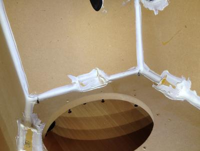

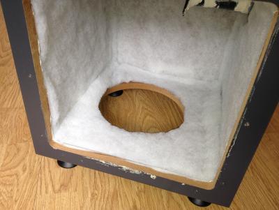

All inside 


After this case upgrade the bass are deeper and louder about 2-3 dB compared with the wooden case with no filling. Compared both with the same master volume and SUB volume settings. This post has been edited by MichalD: Apr 20 2018, 03:44 AM |
|
|
Mar 29 2018, 03:43 AM
Return to original view | Post
#13
|
|
Junior Member
104 posts Joined: Feb 2017 |
QUOTE(asenrzhang @ Mar 20 2018, 07:44 PM) What material are y......needs 32 of them. Do you feel sound quality improvement after replacing these capacitors? Check the new photos i've added to my previous post For the sound quality i´m not sure because i cannot make a direct measurement with factory unit, but i will think of yes becuase of MUSE instead of Jun Fu junk. QUOTE(asenrzhang @ Mar 20 2018, 07:44 PM) Does the color of wires between PSU board and APB board means something or it's just random color? It's just a random color ribbon cable which i had availible. QUOTE(asenrzhang @ Mar 20 2018, 07:44 PM) Again, Nice wiring! Detachable wire, that will make life convenient. And thanks for the model name of pin header (housing): XH (2.54mm). I may try to replace it too. No problem, check the new photos, there are types of connectors i've replaced wroted in the pictures. QUOTE(asenrzhang @ Mar 20 2018, 07:44 PM) Can't believe you replaced the switch too. the old one was all covered by degraded glue and it was less cost and time consuming to replace it for new one instead of cleaning and scraping old glue.QUOTE(asenrzhang @ Mar 20 2018, 07:44 PM) There're two dark green stuff on top of each transfomer, What is that? And what are they used for? Thick sticky tape as only a temporary protection of the tranformers while the board was upside down on the wokbench to avoid damage the transformers because these was the highest parts before all big caps was soldeded. QUOTE(asenrzhang @ Mar 20 2018, 07:44 PM) How do you custom the heat sink (drilling), all by yourself, or bought from shop which provides customing service? I've drawn it in autocad software first and then give the drawing to the shop which manufactured the final product. QUOTE(asenrzhang @ Mar 20 2018, 07:44 PM) I see Nichicon GR series capacitors, which has longer life (10000 hours) than GX series (5000 hours), but I can't found a seller selling this one on local internet market (taobao). Ripple current is slightly smaller (1.4A) than GX series(1.55A), and a little bit taller (40mm) than orginal one (35mm), is that ok? I've choosen all electrolytic caps with the highest possible life rating availible at digikey.com. The height is OK, there is still gap about 7mm between the caps top and heatsink so yes it is OK. QUOTE(asenrzhang @ Mar 20 2018, 07:44 PM) Wait, L11 unsoldered? Only one leg connected to board? Does it work? It is only a inductor connected to one side of LINEAR REG / DIODE heatsink where the other side is not connected anywhere, so it can be as open end and yes it is working well. QUOTE(asenrzhang @ Mar 20 2018, 07:44 PM) Working temperature when power on is around 35-40°C? That's a WOW! I have no idea about 2-3dB louder, but that sounds good. I the summer i expect even higher temperature but i've added bigger FAN (check the new photos) and waiting for hotter days to measure. 2-3dB more measured with iphone app that measures sound level and the units are dB. QUOTE(asenrzhang @ Mar 20 2018, 07:44 PM) About the sound absorbing cotton, does it prevent fire? I mean, if, if there's a spark occured in it sometime for some reason, will it burn the box? By the way, had you tried to replace those operational amplifier chips on APB boards? There're fourteen '072C' and one another on it. The guy whom I'm fixing for want those op-amps to be replaced too, but I don't know what I'm doing if replacing them, and I have no strong feelings that replacing op-amps will improve sound quality. Also, after read some posts, I known oscillation issue may occur after op-amps been replaced. Like I said, I don't know what I'm doing if replacing them. It is some kind of very thin plastic fibres cotton, not a regullar cotton. I've tried to burn it and it melts and it is flamable but i must hold direct fire a couple of seconds to it to set it on fire. I think a small random spark will not set it on fire, only make a small melted spot. For the op-amps i've left them alone, no replacing. Never heard about replacing them is needed. I've got several S750 units. All AMP boards where nearly OK, some of them has broken C40 and one has broken C41. After replacing C40, C41 and for sure C39 was all AMP board fully working. This post has been edited by MichalD: Mar 29 2018, 03:50 AM |
|
|
|
|
|
Apr 5 2018, 03:52 AM
Return to original view | Post
#14
|
|
Junior Member
104 posts Joined: Feb 2017 |
QUOTE(asenrzhang @ Apr 3 2018, 06:56 AM) Okay, that sounds safe enough. Do you have any brand suggestion for it? I found some on local internet market (here, here and here), but I'm not sure about their quality. This type here looks OK, but i've used 1.5cm thickness. Thicker will cause no or very small gap between my modified PSU's PCB traces side and the wadding. I used this. QUOTE(asenrzhang @ Apr 3 2018, 06:56 AM) So, did you reconstructed all these S750 units? Yes, i have now 5 pcs almost fully* reconstructed S750 subwoofer units (5 complete S750 GigaWorks speaker sets). I also have another 6 pcs of PSU boards with replaced all capacitors and connectors as mentioned above, 4 pcs of APB with I/O port board, and 5 pairs of AMP boards, 5 pcs of bass speaker itself, some spare control pods, remotes, cables etc...all this for my future  S1500 TeraWorks project S1500 TeraWorks project *(waiting for ebay for 10mm width, 1mm thick EVA foam self adhesive sealing tape for bass speaker) This post has been edited by MichalD: Apr 5 2018, 03:58 AM |
|
|
Apr 6 2018, 01:04 AM
Return to original view | Post
#15
|
|
Junior Member
104 posts Joined: Feb 2017 |
QUOTE(asenrzhang @ Apr 5 2018, 10:10 AM) By the way, where did you got these units and the individual boards and loud speaker? I only got one extra failed unit from other guy in same city, I couldn't even found one on internet market. I noticed there were some units selling on eBay occasionally, but the shipping cost is too much, or they don't even support shipping internationally. All i got is from ebay and some from local websites selling used units. I collected a lot of everything. Complete subwoofers, complete sets, satellite speakers only, remotes, control pods, PSU board and amp boards, bass speakers only etc and etc...Hanging and searching whole ebay long time. I have collected all from USA, UK and Europe. Some sellers gave me the another subwoofer unit for free or for a small fee, some gave me another PSU board etc... Some ebay seller sell me only internal boards etc etc...It costs a lot of money. But i don't care, i got everything now for my project and a lot of spare parts QUOTE(asenrzhang @ Apr 5 2018, 10:10 AM)  Does the bass speaker need to be repair too like the second fixing of @lex ? Does the bass speaker need to be repair too like the second fixing of @lex ?No, i just want to add a sealing tape to the metal circular part where is the bass speaker screwed to the wooden case for better tightness. Original tape is very thin and is now deformed from previous screwing, so i want to add new seal and a little thicker. |
|
|
Jun 7 2018, 01:14 AM
Return to original view | Post
#16
|
|
Junior Member
104 posts Joined: Feb 2017 |
QUOTE(kotek34 @ Jun 6 2018, 05:20 PM) Unfortunately at the store where I buy electronic components... For C61 try Rubycon BXW series, service life the same but higher ripple current than TXW.This post has been edited by MichalD: Jun 7 2018, 01:15 AM |
|
|
Jun 28 2018, 05:34 AM
Return to original view | Post
#17
|
|
Junior Member
104 posts Joined: Feb 2017 |
QUOTE(nautilus7 @ Jun 27 2018, 11:28 AM) MichalD very nice upgrades!...Can you check please? I've checked it and it is definitely NOT normal, otherwise the capacitor will have no effect. Check capacitor pads related PCB traces for short on other place of the PCB, and under the connector. Try use magnifying glass for zoomed closer view.Here are my old photos of the PCB with caps removed. 

|
|
|
Jun 29 2018, 01:21 AM
Return to original view | Post
#18
|
|
Junior Member
104 posts Joined: Feb 2017 |
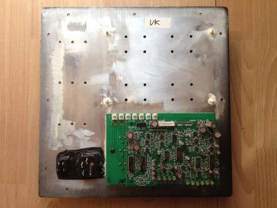
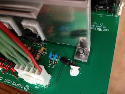
QUOTE(nautilus7 @ Jun 28 2018, 12:16 AM) Hi, thanks for the fast response....connector please? Hello, i've measured that connector (input from power supply board) and all pins have its own potential, the is no short between each other pin. If you found some, there must be a fault.I will test more tomorrow and try to follow the traces on the pcb. Here are two photos with unsoldered power supply connector from the board to view the PCB traces. 

This post has been edited by MichalD: Jun 29 2018, 01:48 AM |
|
|
Jun 29 2018, 01:38 AM
Return to original view | Post
#19
|
|
Junior Member
104 posts Joined: Feb 2017 |
QUOTE(nautilus7 @ Jun 28 2018, 04:01 PM) Fortunately I found the short...(sorry for the blurness). Great, nice job [attachmentid=9885516] btw for the 2x6 pos. connector (flat ribbon to amplifier boards) does it have still shiny pins, or slightly oxidised or corroded? If it are still shiny, there is no need to replace. |
|
|
Jun 29 2018, 02:31 AM
Return to original view | Post
#20
|
|
Junior Member
104 posts Joined: Feb 2017 |
QUOTE(nautilus7 @ Jun 28 2018, 07:08 PM) Hi, thanks for the help...damaged the pads... Hi, yes, i desoldered the 2x6 pin connector with ton of solder and heat it all at once and removed. I damaged the audio processing board some pads while removing the connectors, but i have all carefully repaired and lacquaered.No problem, glad to helped to you. |
| Change to: |  0.0452sec 0.0452sec
 0.33 0.33
 7 queries 7 queries
 GZIP Disabled GZIP Disabled
Time is now: 7th December 2025 - 02:03 AM |
 Quote
Quote