

Unless you're contented with the input caps replacements and the two power caps.. and don't forget the SMDs!.. there's nothing left to do but enjoy the music!

DIY T-Amp User V2, TA2020 AIR CORES!, ~~~~~~~~~~~~~~~~~~~~~~~~~~~~
|
|
 Dec 4 2008, 10:21 AM Dec 4 2008, 10:21 AM
|
 
Senior Member
8,186 posts Joined: May 2005 From: Beaumont, Baile Ath Cliath, EIRE. |
I have maxed out the tweaks, thats why!
Unless you're contented with the input caps replacements and the two power caps.. and don't forget the SMDs!.. there's nothing left to do but enjoy the music! |
|
|
|
|
|
Dec 4 2008, 01:19 PM
|
|
Senior Member
906 posts Joined: Dec 2006 |
My almost completed 3rd T-amp board (supposed to be with full discrete parts) which would eventually find its way into the casing of my 1st T-amp:
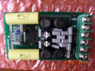
As of now, there are only 2 SMDs remaining on the board: R7 and C5. R7: 8.2K 1W resistor, the discrete resistor from Farnell is ¼W and I don’t quite trust the JP resistor (I bought both). C5: 1.0uF capacitor. I’ve yet to figure out the placement of polarity of Panasonic cap for it. No specification from the schematics, this is output from pin 36 of TA2024 chip going to VDD. The T-amp board with full discrete components doesn’t look too ugly, ya?  |
|
|
Dec 4 2008, 02:01 PM
|
|
Senior Member
8,186 posts Joined: May 2005 From: Beaumont, Baile Ath Cliath, EIRE. |
Y.C.,
Good job there!  Yep.. look great to me!  |
|
|
Dec 4 2008, 08:44 PM
|
|
Senior Member
1,093 posts Joined: Jan 2003 From: SETAPAK, KL |
Y.C. hows the improvement by changing all to discreet components (and the cost too)
, im planning to do the same like you.. |
|
|
Dec 4 2008, 10:15 PM
|

Senior Member
8,046 posts Joined: Jan 2003 |
QUOTE(Y.C. @ Dec 4 2008, 01:19 PM) C5: 1.0uF capacitor. I’ve yet to figure out the placement of polarity of Panasonic cap for it. No specification from the schematics, this is output from pin 36 of TA2024 chip going to VDD. Positive cap terminal to Pin 36. Negative terminal to Pin 33. Hope that helps. This post has been edited by bsl555: Dec 4 2008, 10:16 PM |
|
|
Dec 4 2008, 11:00 PM
|
|
Senior Member
906 posts Joined: Dec 2006 |
Thanks Bsl. I actually soldered the electrolytic cap (C5) with its negative terminal to pin 36 as I thought its other link is to positive side of the 12V DC input by looking at the physical T-amp board. My apology for the incomplete infomation provided.
For info of all, I've fitted the T-amp board with discrete components into the casing of my 1st T-amp in the office after work today. I shall post a picture of it later tonight. As the T-amp board plus all discrete components (apart from my 24-steps 50K discreet attenuator) are brand new and yet to be run-in, I can't really pass a judgment on its sound now but my first impression is a more transparent, more mellow and less clinical sound but slightly softer at the same volume. I thought this T-amp sounds more analogue than my other units. Some of us heard Jazzy's T-amp also replaced with discrete components during our T-amp t/t session and I like it a lot. Cost of discreet components (all from Farnell) used on my T-amp board are as per below. Do note that some of the caps are sold in multiple of 5 or 10. Vishay Roederstein MKT1813 2.2uF 250V coupling caps (2) - RM14.66 Panasonic FC 470uF 25V electrolytic caps (2) - RM4.82 Vishay BC 0.47uF 63V caps (6) - RM15.84 Vishay BC 0.1uF 63V caps (6) - RM7.02 Vishay BC 1000pF 400V caps (4) - RM2.68 Vishay BC 100pF 50V caps (2) - RM2.58 Panasonic Audio Grade 1uF 50V electrolytic caps (2) - RM1.90 Vishay BC 1% Metal Film 20K ohm resistors (4) - RM1.68 Vishay BC 1% Metal Film 10 ohm resistors (2) - RM0.84 Total: RM52.02 If electrolytic caps are to be used (I myself use Panasonic 1.0uF caps in C5 and C17), please observe their polarity. A better way to mount the resistors on the T-amp board would be to let them stand parallel instead of being horizontal as in my case. I could hardly find enough space to mount them in R9 and R10 so much so that I need to remove the 10ohm resistor after having soldered it properly and in the process accidentally lifted the soldering pad of R9 bottom and ended up having to tap its leg to the blotch of solder below C28 bottom. Please exercise care and do not solder and desolder many times as the soldering pads could come out quite easily. If the power buffer caps are to be replaced, the stock caps should to be removed prior to the soldering in of the discrete components. This modification is rather 'absurd' as we are putting in discrete components onto the T-amp board meant for SMDs. It took me 6 hours to complete mine but I feel the outcome to changes to sound of the T-amp is totally fantastic, no regrets. Most important of all, at the end of day we are using it to listen to our music. Enjoy.  This post has been edited by Y.C.: Dec 5 2008, 12:47 AM |
|
|
|
|
|
Dec 4 2008, 11:24 PM
|
|
Senior Member
8,186 posts Joined: May 2005 From: Beaumont, Baile Ath Cliath, EIRE. |
Y.C.,
Excellent work with details there! Shall we have another audition/session? |
|
|
Dec 5 2008, 12:53 AM
|
|
Senior Member
906 posts Joined: Dec 2006 |
Thanks for the compliment, Jazzy
I would be game for another T-amp session but if possible let us have one towards end of the month if the timing is also okay to most who are looking forward to it. |
|
|
Dec 5 2008, 12:56 AM
|
|
Senior Member
8,186 posts Joined: May 2005 From: Beaumont, Baile Ath Cliath, EIRE. |
You're welcome Y.C.!
Sounds good to me Shall we pick a date/venue later?This post has been edited by jazzy939: Dec 5 2008, 12:57 AM |
|
|
Dec 5 2008, 05:37 AM
|
|
Senior Member
906 posts Joined: Dec 2006 |
I promised a picture of my T-amp board with discrete components in casing of my 1st T-amp earlier. Here it is:
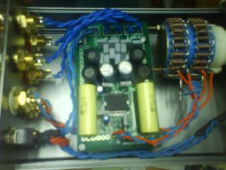
On its sound quality, after playing non-stop for 6 consecutive hours, it is so beautiful now and easily some 20% better in all areas (resolution, expressiveness, micro details, pace, 3D soundstaging, dynamics and even dynamic shadings) in comparison to my 1st board. As I am using a discrete attenuator rather than a carbon type volume pot, I find the high frequencies extended yet not bright sounding to the extent of being unforgiving as reported by Jazzy after his stage 1 mod. Total cost to for discrete components replacement is RM52 as per my earlier comment, almost the price of 1 T-amp board. However, to me, the mod is well worth every sen spent so for those who could handle the soldering iron reasonably well and are deliberating whether to perform the mod or otherwise, my advice would be to go for it and tell me later if I have been incorrect in my assessment. |
|
|
Dec 5 2008, 02:09 PM
|
|
Senior Member
8,046 posts Joined: Jan 2003 |
Good job YC. The passive pot to the PCB is certainly an advantage compared to an external passive pot patched with 1m interconnects. Yours will cut the crap and much shorter signal path. I always believe in the shortest signal path where possible.
|
|
|
Dec 5 2008, 03:48 PM
|
|
Senior Member
906 posts Joined: Dec 2006 |
Thanks for compliment, Bsl.
I've always like passive preamps myself for their sheer resolution and transparency. However, in order for passive preamps to weave their magic, output impedance of our cdp/DAC must be low and their output voltage high. Length of the 2 pairs of interconnects used should be kept as short as possible avoiding unscreened cables and those with high capacitance value. Lastly, the need to match them to power amps capable of higher gain/sensitivity. After some readings, apparently a 10K attenuator is the more commonly adopted value for passive preamps as the aim here would be to increase the input impedance and lower the output impedance. The reknown Audio Synthesis Passion uses a 15K attenuator. As for preamps with active buffering stage, some of the resolution and transparency are sacrificed for more drive and dynamics. |
|
|
Dec 5 2008, 06:53 PM
|
|
Junior Member
74 posts Joined: Oct 2008 |
QUOTE(Y.C. @ Dec 4 2008, 01:19 PM) My almost completed 3rd T-amp board (supposed to be with full discrete parts) which would eventually find its way into the casing of my 1st T-amp: It looks great but I was wondering you must have use some sort of "surgery" instrument to put up all these puzzles (caps) so close together
As of now, there are only 2 SMDs remaining on the board: R7 and C5. R7: 8.2K 1W resistor, the discrete resistor from Farnell is ¼W and I don’t quite trust the JP resistor (I bought both). C5: 1.0uF capacitor. I’ve yet to figure out the placement of polarity of Panasonic cap for it. No specification from the schematics, this is output from pin 36 of TA2024 chip going to VDD. The T-amp board with full discrete components doesn’t look too ugly, ya? |
|
|
|
|
|
Dec 5 2008, 10:52 PM
|

Senior Member
3,160 posts Joined: Jan 2003 From: KLANG! |
QUOTE(Y.C. @ Dec 4 2008, 01:19 PM) My almost completed 3rd T-amp board (supposed to be with full discrete parts) which would eventually find its way into the casing of my 1st T-amp: wow nice!!!
As of now, there are only 2 SMDs remaining on the board: R7 and C5. R7: 8.2K 1W resistor, the discrete resistor from Farnell is ¼W and I don’t quite trust the JP resistor (I bought both). C5: 1.0uF capacitor. I’ve yet to figure out the placement of polarity of Panasonic cap for it. No specification from the schematics, this is output from pin 36 of TA2024 chip going to VDD. The T-amp board with full discrete components doesn’t look too ugly, ya?  im in for TT session if time and work premits , getting back on my feet now  |
|
|
Dec 6 2008, 12:47 AM
|
|
Senior Member
906 posts Joined: Dec 2006 |
Thanks. I only used a Antax 18W soldering iron with fine tip for the soldering job and my fingers to hold them, no 'surgery' tools. I removed the 2 rear ferrite inductors before I desolder the SMDs and solder in the discrete caps and resistors. I should have also removed the 2 front ones as the Panasonic FC470uF 25V caps are way too 'fat'.
QUOTE(cyl1000 @ Dec 5 2008, 06:53 PM) It looks great but I was wondering you must have use some sort of "surgery" instrument to put up all these puzzles (caps) so close together Thanks. We certainly look forward to have you around this time around. QUOTE(xtorm @ Dec 5 2008, 10:52 PM) wow nice!!! im in for TT session if time and work premits , getting back on my feet now This post has been edited by Y.C.: Dec 6 2008, 12:57 AM |
|
|
Dec 7 2008, 07:34 PM
|
|
Senior Member
906 posts Joined: Dec 2006 |
After 3 days of continuously being powered up by a Meanwell S-50-12 SMPS and playing music several hours a day, I dare pronounce that my discrete parts T-amp will take on and give many highend amplifiers a run for money. What it could not produce in quantity (huge wattage) is compensated by the sheer quality which oozes from it.
|
|
|
Dec 7 2008, 08:23 PM
|
|
Senior Member
8,186 posts Joined: May 2005 From: Beaumont, Baile Ath Cliath, EIRE. |
and we believe you!
|
|
|
Dec 9 2008, 02:14 PM
|
|
Senior Member
906 posts Joined: Dec 2006 |
I agree fully with the remark of "good sound has universal standards" that I read in an online article rather than the frequently uttered defensive ones such as "I like how my system sound and I don’t give a damn to how others perceive it".
I have the pleasure of having the presence of a fellow forumer over at my place during the weekend to listen to my main system. Towards the end of the listening session, he pointed out that my system sounded a wee bit too fast that the low bass just does not have enough 'grunt'. Since I have always like my music to sound fast and rhythmic, this realisation came as a shock to me. I later zoom down and thought the culprit to be my vdH First interconnects as I have adopted the best compromise (I wanted to tame the rather harsh digital sound to make it sound more closer to analogue) here for the least trade-off. Apparently the trade-off is not the least now or so it seems. The equipment used as benchmark to illustrate the shortcoming further is none other than my T-amp with discrete components which is much more transparent and sounds airier with better decay. I think the fellow forumer may find the sound of T-amp to be acceptable now. This post has been edited by Y.C.: Dec 9 2008, 08:24 PM |
|
|
Dec 9 2008, 05:20 PM
|
|
Senior Member
8,186 posts Joined: May 2005 From: Beaumont, Baile Ath Cliath, EIRE. |
Y.C.,
Thanks for the update! I had a 'stranger' last weekend.. an astro installer installing my astro hardwares. While clearing up his paper work, I played my T-Amp setup. He said my system sounds like a RM10,000 system! He also said he has a friend that own a HiFI shop and spend lots of time listening to the HiFi equipments.. I showed him the tiny T-Amp and he was impressed. The only comment he gave is that he likes to listen to percussions and thats lacking in my system. No problemo. The songs that I played don't have much percussions anyway! Thats one up for the T-Amp! This post has been edited by jazzy939: Dec 9 2008, 05:24 PM |
|
|
Dec 11 2008, 10:19 AM
|
|
Senior Member
906 posts Joined: Dec 2006 |
Jazzy, it looks like we are the only ones raving about out T-amps now. Anyhow, enjoy our music with our T-amps.
 |
| Change to: |  0.0352sec 0.0352sec
 0.54 0.54
 6 queries 6 queries
 GZIP Disabled GZIP Disabled
Time is now: 20th December 2025 - 02:46 PM |
 Quote
Quote