

I took another multimeter from friend and checked again - is good now. I have connected the amplifiers boards and... the S750 is working

Thanks again
This post has been edited by kotek34: Oct 1 2016, 01:12 AM
PC Audio Creative GigaWorks S750 7.1 speaker repair, A short guide and info with pictures...
|
|
 Oct 1 2016, 01:11 AM Oct 1 2016, 01:11 AM
|

Junior Member
16 posts Joined: Sep 2016 |
Hey,
I took another multimeter from friend and checked again - is good now. I have connected the amplifiers boards and... the S750 is working Thanks again This post has been edited by kotek34: Oct 1 2016, 01:12 AM |
|
|
|
|
|
Oct 1 2016, 12:40 PM
|
|
Junior Member
68 posts Joined: Apr 2015 From: China |
QUOTE(kotek34 @ Oct 1 2016, 01:11 AM) Hey, Congratulations! I took another multimeter from friend and checked again - is good now. I have connected the amplifiers boards and... the S750 is working Thanks again   |
|
|
Oct 10 2016, 10:29 PM
|
|
Newbie
1 posts Joined: Oct 2016 |
Hi everyone,
I've had issues with my S750 set up for some time now and tried to get a local repair (I'm in Muscat, Oman). Long story short is I can't get it repaired locally and have zero expertise in this so I am going to try to make the best of what I have. Is it possible to use the subwoofer on its own and scrap the amp part of the unit inside? Basically I would like to use the subwoofer in the same way as a stand alone satellite speaker but have the following questions. 1 - Is it possible to have a direct line to the subwoofer of 8ohms? This is the question I was asked by the guy who will be working on this for me. I don't have any technical knowledge so please give as simple an answer as possible - thanks. 2 - Would I need to power the subwoofer if I'm only using it as a satellite speaker? 3 - I will be buying a separate amp, Onkyo TX-SR444 7.1 - Channel A/V Receiver. Will this be sufficient for the job? I'm loathed to throw the S-750 away because the speakers are great it's just crap components inside the subwoofer/amp part that ruins a really good speaker system. Thanks for your help in advance and apologies for my almost complete lack of knowledge. |
|
|
Nov 16 2016, 12:46 AM
|
|
Newbie
1 posts Joined: Nov 2016 |
Hi all, Im learning a lot with this tread and unfortunately my Creative died after about 10 years of usage... reading this tread gave me another hope to fix the issue...
Question about the Y capacitor mentioned, does anyone can let me know the possible replacement for this one? Does anyone know if this one can be used? http://www.digikey.co.uk/product-detail/en...5838-ND/4382721 Thanks |
|
|
Dec 1 2016, 12:06 AM
|
|
Newbie
1 posts Joined: Nov 2016 |
Hi folks ,
Thanks everyone who has contributed in this topic. Now here is my odyssey with Gigaworks S750. I have used my set since 2009 up until July 2015 when it refused to power on again . As I was out of warranty since like 2011 I went and bought Logitech Z-906 (which BTW work very good so far) This year I updated my HTPC to sport UHD res , and then came the idea to try and resurrect the S750 (also by chance I actually saw that the green LED that indicates power is flashing , but the set does not power on) and I decided to take them to the repair shop located in my apartment building - it so happens that what could best be translated as the building superintendant happens to own that said shop and they are good at this - been here for over 20 years by now . They repaired the PSU in less than 2 hours .Set was working just fine since then ( 14th this month ) up until about a week ago I noticed that the Rear Left channel goes offline randomly - I tested with a different system with an older X-Fi Sound Blaster - the old Xtreme Music PCI with 2 MBs of ram - barely managed to reproduce the 3:4 cable that I had lost and the Rear Left worked ( well for few simple speaker tests) and I decided that it is indeed the speaker set. Then I hooked up the set to the HTPC(Using X-fi Titanium PCI-x card) and Rear Left worked for about 1-2 hours and stopped again - tried moving jacks from the 4:4 cable around - turns out the output is coming from the SB . Dropped them earlier today downstairs and asked the guy to hook up a 12V output for a fan ( have a vague memory that people used this as a solution to the heat output and it worked) and advised on this issue. After 4 hours they called me to pick the set up - they have hooked a walkman for 40+ minutes to rear channel output and it worked - so I picked up the set and went on to test - not surprisingly the Rear Left channel went poof shortly after . So I found this topic on the web . Now I have 2 major issues that are plaguing the set : The proverbial insta power of upon clicking the switch ( which is not that pronounced now , but is still there) And channels randomly going off - for a brief period Front Left & Rear Right have been gone , could not replicate it , but still the Rear Left issue is there I suppose the 25V to 63V change should address the Insta-power-off issue , and cleaning of the annoying glue should resolve the channel going randomly off issue . By the way , I am somewhat skilled in the area of fixing electronics( at one point in time back in 2011 I actually operated a BGA station for repairing PS3s , and old laptop/desktop MainBoards & VGA cards) but as imagined, my skills are somewhat rusty. What I consider proper course of action is to change the C®apacitors to proper quality ones , and cleaning of the glue . If it will help in giving advise to me , I will provide screenshots of the components This post has been edited by VolF3r: Dec 1 2016, 12:07 AM |
|
|
Jan 6 2017, 12:37 AM
|
|
Junior Member
33 posts Joined: Jul 2016 |
QUOTE(asenrzhang @ Sep 5 2016, 05:08 PM)  Disclaimer: I'm not a professional electronic engineer, not even an amateur, so, take the advice at your own risk. Disclaimer: I'm not a professional electronic engineer, not even an amateur, so, take the advice at your own risk.I know how frustrated it is when get into puzzle. I was there before, I'm a beginner in electronic engineering too, I spent a year to find out what caused my fuse blown again and again. But hey, we're not in AA meeting in Hollywood movies, "AA is for quitters  ", said by Bubba J. ", said by Bubba J.You may read @lex (OP)'s posts 2.5 years ago. Those are two replies to another user's "resistor blew" issue after he replaced Q4, I don't know if it can help, but you can have a look, and check the components listed in the posts. - https://forum.lowyat.net/index.php?showtopi...post&p=66540534 - https://forum.lowyat.net/index.php?showtopi...post&p=66570064 I'm back and happy new year ! So today, I decided to re-assemble my S750 again after a sooo long time ! I soldered back all the diods, PNP, changed the 3x IRF740, and let's go to the testing : - No heatshrink mounted, powered on with CN4 and CN5 unplugged : OK - No heatshrink mounted, powered on with CN5 plugged and CN4 unplugged : OK - Same thing, but I pugged CN4 too (twice are now plugged) : and here something went wrong (heard a "pffff" noise and fuse blown) So it could be one of the amplifier board which are defective ? I know I didin't take off the glue on these boards, perhaps that could be the wrong thing ? I take a short look to find what could have blown (the "pfff" sound) but didn't find something yet. Perhaps another capacitor ?!? Any ideas ? |
|
|
|
|
|
Jan 6 2017, 03:04 AM
|
|
Junior Member
68 posts Joined: Apr 2015 From: China |
Disclaimer: I'm not a professional electronic engineer, not even an amateur, so, take the advice at your own risk. QUOTE(rsseco @ Jan 6 2017, 12:37 AM) Hi ! Happy new year!I'm back and happy new year ! QUOTE(rsseco @ Jan 6 2017, 12:37 AM) So today, I decided to re-assemble my S750 again after a sooo long time ! Did you replaced all the electrolytic capacitors on PSU board?I soldered back all the diods, PNP, changed the 3x IRF740, and let's go to the testing : - No heatshrink mounted, powered on with CN4 and CN5 unplugged : OK - No heatshrink mounted, powered on with CN5 plugged and CN4 unplugged : OK - Same thing, but I pugged CN4 too (twice are now plugged) : and here something went wrong (heard a "pffff" noise and fuse blown) Since we are beginners, no enough experience and equipment to check, I would like to follow @lex's guide to replace all electrolytic capacitors on PSU board first, then do the test. QUOTE(rsseco @ Jan 6 2017, 12:37 AM) So it could be one of the amplifier board which are defective ? I know I didin't take off the glue on these boards, perhaps that could be the wrong thing ? Not sure it's AMP board's fault or not. The glues for biggest capacitor on AMP board are 'white' glues, I think it don't need to be removed.I take a short look to find what could have blown (the "pfff" sound) but didn't find something yet. Perhaps another capacitor ?!? Any ideas ? I don't know what the 'pfff' sound came from, maybe it came from the blown fuse itself. I would like to do the following before testing
------------- By the way, I bought a failed subwoofer, and try to repair it for fun. The previous owner said it does not power at all, no LED light, nothing. After fixing, LED on back plate and control pods are back, press the "STANDBY/POWER" button, the "MASTER" led turns on, but it doesn't actually power up: no click sound came out from the relay. I measured the output voltage of CN6, all the voltage reading values are about half of value it should be. Hope somebody can help me to find out the source issue. 

All the electrolytic capacitors on PSU board had been replaced (but the 35V/100μF were replaced with 35V/220μF, because I forgot to bought them...) 
Update 1 (2017-01-07 02:50) I just desoldered the opto coupler (U2), clean it, check it ( There's explosion sign under C62 which is near to the opto coupler, I guess the explosion had affected the feedback circuit somehow. Update 2 (2017-01-08 00:50) The subwoofer does not produce sounds even the main power is on. After careful check, I found that the +24V and -24V voltage are still low (around +17V and -17V), and 4 terminals of VH connector of power lines from/ AMP boards are broken (the tongue is broken/missing). 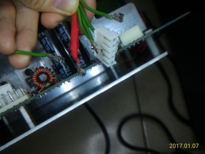
So I bought some opto couplers and terminal components, waiting for the arrival...  Update 3 (2017-01-10 20:30) Good news, after I replaced the optocoupler (U2), the subwoofer can produce sounds now ! In update 1, I thought it's okay, but it's not! The resistance between 3 and 4 pin/leg is about 1040 Ohm, in both direction, without powered on. ------------- Just for fun: My PSU of desktop computer failed last week. Symptom: Keeps rebooting without BIOS booted. I disassembled the PSU, found two capacitors in it, and their rating are the same as S750's: 200V/470μF/22mmx35mm. I measured the capacitance of them, only 320μF (68%) left. So I replaced them with two capacitors which were desoldered from S750, guess what, IT WORKS! 
But for long term consideration, I bought two new Nichicon PW series capacitors and replaced those two CapXon capacitors. 
This post has been edited by asenrzhang: Jan 10 2017, 09:47 PM |
|
|
Jan 8 2017, 05:51 AM
|
|
Junior Member
33 posts Joined: Jul 2016 |
Hi,
It's good to read you again ! No, I haven't replaced any other capacitors (only the 470uF ones). As wrote before, I wanted to repair the set as costless as possible... I need to know how much it will cost me to replace all of them, but I hope it will really be repaired after that. Today, I visually check the upper Amp board ; nothing to notice. But on the power board, I notice that the C70 was a little "bumped" on the top (the same cap which had exploded as the set died) ; I removed the protection, but didn't found any electrolite leak. Maybe the "pfff" sound could came from it even so. On the back of the board, the + pole of C70 is wonky, so I think it cames from here. I will try to buy genuine Capacitors first, as you found that mines were faked. |
|
|
Jan 9 2017, 02:47 AM
|
|
Junior Member
68 posts Joined: Apr 2015 From: China |
QUOTE(rsseco @ Jan 8 2017, 05:51 AM) Hi, It's good to read you again ! No, I haven't replaced any other capacitors (only the 470uF ones). As wrote before, I wanted to repair the set as costless as possible... Well, if budget is the primary concern, this could lead you to a dead loop: 1. You don't have the ability to diagnose the issue. 2. You buy least components to replace suspicious failed components. 3. You found more suspicious failed components, or, the previous replacements which may not be genuine introduced more unexpected symptom. 4. You may need buy more components which cost more including delivery cost and time. (dead loop) So I will suggest to follow @lex's guide, replace all electrolytic capacitors, then do the test. This is because that electrolytic capacitors are the most easy-to-fail components, replace them can clean the road to next step. QUOTE(rsseco @ Jan 8 2017, 05:51 AM) I need to know how much it will cost me to replace all of them, but I hope it will really be repaired after that. Some users had already made a buy-list of capacitors, you can do a quick math according those lists.QUOTE(rsseco @ Jan 8 2017, 05:51 AM) Today, I visually check the upper Amp board ; nothing to notice. If the subwoofer is running in normal condition, then C70 is the last one of the 4 200V/470μF capacitors that will become bulged -- because it located at the bottom -- heat go up, not go down.But on the power board, I notice that the C70 was a little "bumped" on the top (the same cap which had exploded as the set died) ; I removed the protection, but didn't found any electrolite leak. Maybe the "pfff" sound could came from it even so. On the back of the board, the + pole of C70 is wonky, so I think it cames from here. I will try to buy genuine Capacitors first, as you found that mines were faked. So if C70 be bulged now in just testing stage (no heavy load, no long time running), it could be capacitor's fault. About the unsteady solder joint of + leg of C70, make sure your solder points are completely soldered to the legs. And the solder pads of these 4 capacitors are easy to get off (I really hate Snap-In legs), if so, make sure the solder pads are completely off and then make a 'L' shape connector to fix the circuit, this will make the solder joint steady. This post has been edited by asenrzhang: Jan 9 2017, 02:57 AM |
|
|
Jan 10 2017, 10:05 PM
|
|
Junior Member
68 posts Joined: Apr 2015 From: China |
QUOTE(asenrzhang @ Jan 6 2017, 03:04 AM) ... Good news, after I replaced the optocoupler (U2), the subwoofer can produce sounds now !------------- By the way, I bought a failed subwoofer, and try to repair it for fun. The previous owner said it does not power at all, no LED light, nothing. After fixing, LED on back plate and control pods are back, press the "STANDBY/POWER" button, the "MASTER" led turns on, but it doesn't actually power up: no click sound came out from the relay. I measured the output voltage of CN6, all the voltage reading values are about half of value it should be. Hope somebody can help me to find out the source issue.
All the electrolytic capacitors on PSU board had been replaced (but the 35V/100μF were replaced with 35V/220μF, because I forgot to bought them...)
Update 1 (2017-01-07 02:50) I just desoldered the opto coupler (U2), clean it, check it (seems fine, but I'm not sure), and I soldered it back, luckily, I can turn on the main power now. There's explosion sign under C62 which is near to the opto coupler, I guess the explosion had affected the feedback circuit somehow. Update 2 (2017-01-08 00:50) The subwoofer does not produce sounds even the main power is on. After careful check, I found that the +24V and -24V voltage are still low (around +17V and -17V), and 4 terminals of VH connector of power lines from/ AMP boards are broken (the tongue is broken/missing).
So I bought some opto couplers and terminal components, waiting for the arrival... ------------- ... In update 1, I thought it's okay, but it's not! The resistance between #3 and #4 pin/leg is about 1040 Ohm, in both direction, without powered on. So I bought some new optocouplers (I actually bought two times, wrong type at the first time: Avago ACPL-817 C, which the rank is not right. It should be rank A, so I bought SHARP PC817 A at the second time), replaced the old one, the failed one, now the speaker can make noise now (although it still have some small issues such as low volume on some channels, I suspect it's like the issue of @lex's second fix: some channels random off). So, I make a memo here in case I encountered same issue next time: When got low secondary voltage of transformer 3 (while the input voltage is normal, around 300V), check the feedback circuit, including the optocoupler (U2). This post has been edited by asenrzhang: Jan 13 2017, 01:08 PM Attached thumbnail(s) 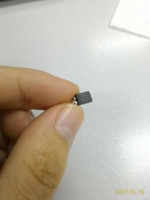
|
|
|
Feb 16 2017, 08:06 PM
|
|
Junior Member
104 posts Joined: Feb 2017 |
Hello to all, i have sucesfully repaired my S750 set few days ago (both C40 on AMP boards were exploded only, but replaced all big caps and some smaller caps on PSU board even if no one was bulged) (big thanks for this forum and to the people for their helpfull topics), i want to buy another please can somebody tell me what is the difference in the PSU board between US 110V and EU 230V version? In the PSU scheme i found something about R32, R31 and R3. Simply by following these three "resistors" (0 ohm links or open links) can i adapt the PSU board to 230V or 110V input voltages? Thanks for soon reply.
MichalD. Attached thumbnail(s) 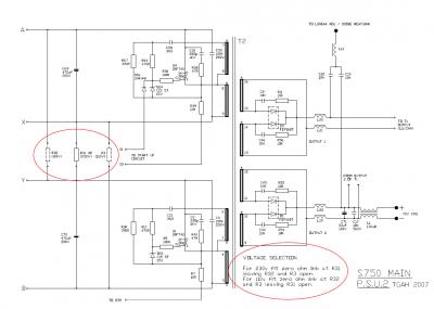
|
|
|
Feb 17 2017, 06:38 PM
|
|
Junior Member
68 posts Joined: Apr 2015 From: China |
QUOTE(MichalD @ Feb 16 2017, 08:06 PM) ...what is the difference in the PSU board between US 110V and EU 230V version? I can tell the only different is just different connections of those three 0Ω resistors, as you already found it.QUOTE(MichalD @ Feb 16 2017, 08:06 PM) In the PSU scheme i found something about R32, R31 and R3. Simply by following these three "resistors" (0 ohm links or open links) can i adapt the PSU board to 230V or 110V input voltages? Thanks for soon reply. With proper modification (the schematics already figure it out), you can make the PSU works on 230V or 110V.110V to 220~240V modification should be easy, because you don't need to buy another 0Ω resistor. 220~240V to 110V modification is easy too, but you need buy another 0Ω resistor. |
|
|
Feb 17 2017, 08:50 PM
|
|
Junior Member
104 posts Joined: Feb 2017 |
QUOTE(asenrzhang @ Feb 17 2017, 11:38 AM) I can tell the only different is just different connections of those three 0Ω resistors, as you already found it. Great, thank you for your assurance.With proper modification (the schematics already figure it out), you can make the PSU works on 230V or 110V. 110V to 220~240V modification should be easy, because you don't need to buy another 0Ω resistor. 220~240V to 110V modification is easy too, but you need buy another 0Ω resistor. |
|
|
|
|
|
Mar 11 2017, 10:01 PM
|
|
Junior Member
5 posts Joined: Mar 2017 |
hey guys , i repaired my own s750 but with a professional engineer and it working only for 2 months ! anyway i was so happy of that but when it was on i hear a sound like explode and my pod lights gets off and blinking power light on the back of the sub-woofer , anyway i open the subwoofer and i saw a IRF740 is exploded ! and 1 of the C60 or C61 was a bit shaking i mean its not well connected to the board anyway i go to a electric repair shop and i ask him to replace the IRF740 and connect the C60 or C69 to the board again , i came home and connect the power board to the IO-Board and amp 1 , amp 2 but guess what still like before i replace the IRF740 and C60 connection repair nothing changed at all so i try to disconnect the AMP 1 and AMP 2 from the power board and then when i disconnect the AMP2 wire from the power board the green light instantly get back and even i can turn on it full , but if i connect the amp2 instantly the power goes off and green power light start blinking !!! i want to know the problem is from AMP board or still maybe there is a problem with the Power board ? because i just want to know if this issue came from the AMP board i will check it again for fault parts but if still maybe there is a problem with power board i will try to change all caps or anything i can again for make sure its not the power board problem , another question can anyone tell me the right voltage in a working fine and stable sub-woofer for AMP board ?
if i know maybe i check the powers first to understand the problem is still because of power board or amp board , ty for this topic it will help a lot of people . and another thing i forgot to mean it after some disconnect and reconnecting again the amp 2 board that cause the power off the C60 get exploded ( only smoke not so much sound ) anyway what kind of the problem is that !?!?! i really feeling disappointed . i waiting for an answer..... |
|
|
Mar 11 2017, 10:11 PM
|
|
Junior Member
5 posts Joined: Mar 2017 |
QUOTE(asenrzhang @ Feb 17 2017, 02:08 PM) I can tell the only different is just different connections of those three 0Ω resistors, as you already found it. hey man , ty for ur reply's i read all of them and i have the same problem like the other guy said if he connect the amp board to the power board the green light is blinking and if the amp board disconnected from the power board the green light get back instantly . i hope u answer me or give me some tips i really love s750 setup because its really amazing u won't believe that i use it with my old sound card sound blaster audigy 2 zs with windows 10 64-bit and it sounds lovely !! im waiting for ur answer . u can check my previous reply here ( i mean full detailed problem ) tyWith proper modification (the schematics already figure it out), you can make the PSU works on 230V or 110V. |
|
|
Mar 12 2017, 01:30 AM
|
|
Junior Member
68 posts Joined: Apr 2015 From: China |
Again, I'm not a professional engineer, so take the advises at your own risk!
QUOTE(golestani @ Mar 11 2017, 10:01 PM) ... I would like to do this test (let me call it Test Case for AMP Board 2) to identify the source:so i try to disconnect the AMP 1 and AMP 2 from the power board and then when i disconnect the AMP2 wire from the power board the green light instantly get back and even i can turn on it full , but if i connect the amp2 instantly the power goes off and green power light start blinking !!! i want to know the problem is from AMP board or still maybe there is a problem with the Power board ? disconnect AMP board 1, connect AMP board 2, then power on to see if the back LED blinking or not. QUOTE(golestani @ Mar 11 2017, 10:01 PM) because i just want to know if this issue came from the AMP board i will check it again for fault parts but if still maybe there is a problem with power board i will try to change all caps or anything i can again for make sure its not the power board problem Most blinking LED issues of S750 are caused by bad capacitors.I say "most", not "all", because when I repair AMP board 2, there's one time, when I try to mount the AMP board 2 back, I leave one screw loosely, very loosely --> this caused back LED blinking too, I guess the screw make a circuit somehow between the back plate and hint sink of AMP board 2. QUOTE(golestani @ Mar 11 2017, 10:01 PM) another question can anyone tell me the right voltage in a working fine and stable sub-woofer for AMP board ? CN4 & CN5: [1] [2] [3] [4] [5](pin for RED wire)
QUOTE(golestani @ Mar 11 2017, 10:01 PM) and another thing i forgot to mean it after some disconnect and reconnecting again the amp 2 board that cause the power off the C60 get exploded ( only smoke not so much sound ) anyway what kind of the problem is that !?!?! I don't know. I mean it could be the fault of PSU board, or fault of AMP board 2, or both. |
|
|
Mar 12 2017, 05:23 AM
|
|
Junior Member
5 posts Joined: Mar 2017 |
QUOTE(asenrzhang @ Mar 11 2017, 09:00 PM) Again, I'm not a professional engineer, so take the advises at your own risk! for the first test yeah , the only way i got green light blinking when i connect amp board 2 its not matter its connected solo or connected with I/O and AMP 1 board , so i think maybe its because of AMP 2 problem but there is nothing to see with the eyes , and again i changed 4 200v 470uf and still 1 of the CAP get very hot if i let it go im sure it will explode again ! and its only happened when i turn on the PSU with POD or remote control ( the only way i can turn the subwoofer on is when i disconnect the AMP2 (( the one with 3 bash IC's )) and when i turn it on the CAP C60 getting hot i mean too much hot in 10 or 20 second and if i dont disconnect the cable from the electric im sure it will explode again like last time it already did !I would like to do this test (let me call it Test Case for AMP Board 2) to identify the source: disconnect AMP board 1, connect AMP board 2, then power on to see if the back LED blinking or not. Most blinking LED issues of S750 are caused by bad capacitors. I say "most", not "all", because when I repair AMP board 2, there's one time, when I try to mount the AMP board 2 back, I leave one screw loosely, very loosely --> this caused back LED blinking too, I guess the screw make a circuit somehow between the back plate and hint sink of AMP board 2. CN4 & CN5: [1] [2] [3] [4] [5](pin for RED wire)
I don't know. I mean it could be the fault of PSU board, or fault of AMP board 2, or both. so i just want to know if u know where this problem cause only for C60 CAP its happening . still i don't know what is the problem maybe C60 cap didn't connected to the board well and the C60 is the power source of the AMP2 board so if i connect it to the power board , power board will understand the power is on problem or even there is a problem with AMP2 so it won't let u turn on the sub-woofer ! i still don't understand it at all but i won't give up so easy ! after first time i spent about 80 dollar to fix it , it only worked for 2 months and its make me feel so bad  if my s750 will get back to live again i will get all of the AMP and IO and Power board out of the sub-woofer and i will make a custom box for AMP,etc and just a small wire get into the sub-woofer for the sub-woofer sound , and i will keep the amp and other board cool with a FAN or something else maybe i put it in the freezer ) but i don't want to lose it again only because of poor design of the amp and power when there is no air coming in and out . if my s750 will get back to live again i will get all of the AMP and IO and Power board out of the sub-woofer and i will make a custom box for AMP,etc and just a small wire get into the sub-woofer for the sub-woofer sound , and i will keep the amp and other board cool with a FAN or something else maybe i put it in the freezer ) but i don't want to lose it again only because of poor design of the amp and power when there is no air coming in and out . |
|
|
Mar 12 2017, 03:45 PM
|
|
Junior Member
68 posts Joined: Apr 2015 From: China |
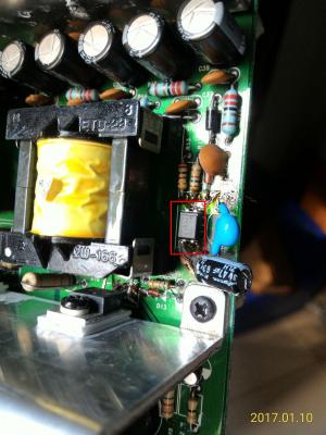
QUOTE(golestani @ Mar 12 2017, 05:23 AM) ... Let me confirm these information:and again i changed 4 200v 470uf and still 1 of the CAP get very hot if i let it go im sure it will explode again ! and its only happened when i turn on the PSU with POD or remote control ( the only way i can turn the subwoofer on is when i disconnect the AMP2 (( the one with 3 bash IC's )) and when i turn it on the CAP C60 getting hot i mean too much hot in 10 or 20 second and if i dont disconnect the cable from the electric im sure it will explode again like last time it already did ! so i just want to know if u know where this problem cause only for C60 CAP its happening . still i don't know what is the problem maybe C60 cap didn't connected to the board well and the C60 is the power source of the AMP2 board so if i connect it to the power board , power board will understand the power is on problem or even there is a problem with AMP2 so it won't let u turn on the sub-woofer ! (1) You replaced C59 & C60 & C69 & C70 (2) You disconnected AMP 2 (3) You use POD or remote control to power on (4) Still, you got C60 very hot in seconds (without AMP 2) And the voltage of your power line is 110V or 220V~240V? If C60 is the only capacitor which becomes hot, maybe you need to check components in the following picture: 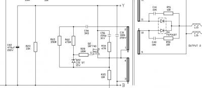
Especially Q2 (IRF740) and D4 (FEP16DT), if Q2 is the one exploded and been replaced in the repair shop, then focus on D4. QUOTE(golestani @ Mar 12 2017, 05:23 AM) i still don't understand it at all but i won't give up so easy ! after first time i spent about 80 dollar to fix it , it only worked for 2 months and its make me feel so bad If you successfully put PSU & AMP & IO boards to another box, please share your experience. if my s750 will get back to live again i will get all of the AMP and IO and Power board out of the sub-woofer and i will make a custom box for AMP,etc and just a small wire get into the sub-woofer for the sub-woofer sound , and i will keep the amp and other board cool with a FAN or something else maybe i put it in the freezer ) but i don't want to lose it again only because of poor design of the amp and power when there is no air coming in and out . such as
This post has been edited by asenrzhang: Mar 12 2017, 04:02 PM |
|
|
Mar 12 2017, 06:34 PM
|
|
Junior Member
5 posts Joined: Mar 2017 |
QUOTE(asenrzhang @ Mar 12 2017, 11:15 AM) Let me confirm these information: I'm using the 220v~240v for sure .(1) You replaced C59 & C60 & C69 & C70 (2) You disconnected AMP 2 (3) You use POD or remote control to power on (4) Still, you got C60 very hot in seconds (without AMP 2) And the voltage of your power line is 110V or 220V~240V? If C60 is the only capacitor which becomes hot, maybe you need to check components in the following picture:
Especially Q2 (IRF740) and D4 (FEP16DT), if Q2 is the one exploded and been replaced in the repair shop, then focus on D4. If you successfully put PSU & AMP & IO boards to another box, please share your experience. such as
and yeah only C60 will get hot after I turn on sub with POD only way POD will get alive is disconnecting the amp board from the power board and in standby mode I think everything is ok but for sure I have to disconnect amp board to see the lights on pod and for sure I will check that D4 and see what is going on. if my set get alive for sure I will share all photos how to do that , and for the thing u said about how to fill the hole u make for wires to get into the sub-woofer box its really easy u just need to use a drill to open a hole as much small as u can then after ur wires get enough into the hole u can use glue to close the hole I already did it when I got my input power fuse and other par get die ! right now I have no power in socket on the back of the sub-woofer I put him out of the subwoofer and I use a glue and peace of wood to fill the back of the sub-woofer and as I said if the my s750 gets alive 100% I will make another box for all other parts and put a fan back of the box to get the air get our or get into the box of hot stuffs )I will share them with photos or some parts with video . because its only works for 2 months after professional repair and for sure the problem is hot box because I can't play my s750 at high volume so it can cool down him self ! and I use it on 2 or 3 lights volume on the pod mostly so sub-woofer can't change the air in the box . I think they use sub-woofer for changing the air not to bashing around ) 8" sub-woofer in the box  for ventilation for ventilation but its only works when u constantly play a music with high volume at least 5 green lights on the volume bar on the pod |
|
|
Mar 12 2017, 06:36 PM
|
|
Junior Member
5 posts Joined: Mar 2017 |
QUOTE(asenrzhang @ Mar 12 2017, 11:15 AM) Let me confirm these information: I forgot to ask can I use 250V 470uf for C60 cap or they all should be 200v only ?(1) You replaced C59 & C60 & C69 & C70 (2) You disconnected AMP 2 (3) You use POD or remote control to power on (4) Still, you got C60 very hot in seconds (without AMP 2) And the voltage of your power line is 110V or 220V~240V? higher voltage will help or its just not important ? |
| Change to: |  0.0438sec 0.0438sec
 0.29 0.29
 6 queries 6 queries
 GZIP Disabled GZIP Disabled
Time is now: 15th December 2025 - 07:38 AM |
 Quote
Quote