

anyone can help me repair my gigaworks t40?
PC Audio Creative GigaWorks S750 7.1 speaker repair, A short guide and info with pictures...
PC Audio Creative GigaWorks S750 7.1 speaker repair, A short guide and info with pictures...
|
|
 Mar 12 2017, 06:37 PM Mar 12 2017, 06:37 PM
Show posts by this member only | IPv6 | Post
#381
|
 
Junior Member
540 posts Joined: Jan 2008 |
anyone can help me repair my gigaworks t40?
|
|
|
|
|
|
Mar 12 2017, 08:35 PM
|
|
Junior Member
68 posts Joined: Apr 2015 From: China |
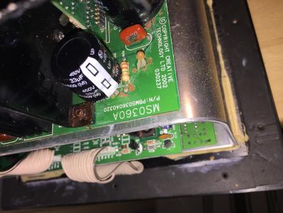
QUOTE(golestani @ Mar 12 2017, 06:36 PM) I forgot to ask can I use 250V 470uf for C60 cap or they all should be 200v only ? It should be okay.higher voltage will help or its just not important ?  Just pay attention of size of the capacitor. Usually it will be either taller (Height) or fatter (Dimension), so pick a same size & high ripple current & long life & genuine one could cost some time. |
|
|
Mar 12 2017, 09:05 PM
|
|
Junior Member
68 posts Joined: Apr 2015 From: China |
QUOTE(golestani @ Mar 12 2017, 06:34 PM) .. WOW, is that really so easy? I'm more like a computer software guy rather than a hardware guy, drilling & gluing & wiring means it's hard to me and for the thing u said about how to fill the hole u make for wires to get into the sub-woofer box its really easy u just need to use a drill to open a hole as much small as u can then after ur wires get enough into the hole u can use glue to close the hole I already did it when I got my input power fuse and other par get die ! right now I have no power in socket on the back of the sub-woofer I put him out of the subwoofer and I use a glue and peace of wood to fill the back of the sub-woofer  QUOTE(golestani @ Mar 12 2017, 06:34 PM) ... Usually, I stay with the default 4 (||||_ _ _) volume, and I didn't feel much heat in nowadays (I mean, winter/spring), but I do feel much heat in summer.and for sure the problem is hot box because I can't play my s750 at high volume so it can cool down him self ! and I use it on 2 or 3 lights volume on the pod mostly so sub-woofer can't change the air in the box . I think they use sub-woofer for changing the air not to bashing around  ) 8" sub-woofer in the box ) 8" sub-woofer in the box  for ventilation for ventilation but its only works when u constantly play a music with high volume at least 5 green lights on the volume bar on the pod I guess music with low frequency may help the air flow across the box, you can feel the air flow at the inverted cube (the big hole on the left side). On the other hand, play low frequency music may cost more power, hence more heat are generated  . . |
|
|
Mar 16 2017, 11:48 AM
|

Junior Member
265 posts Joined: Apr 2013 |
Where to send for 110V to 220~240V modification?
|
|
|
Mar 29 2017, 04:11 AM
|
|
Junior Member
104 posts Joined: Feb 2017 |
QUOTE(azuradaniel @ Mar 16 2017, 04:48 AM) Where to send for 110V to 220~240V modification? You can do it yourself, you just need soldering iron, solder, and basic soldering skills. Just look at the pictures. There is "conversion manual" and the other image is 230V version.Attached thumbnail(s) 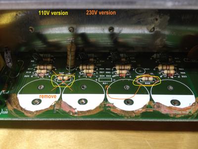

|
|
|
Jun 10 2017, 11:14 PM
Show posts by this member only | IPv6 | Post
#386
|
|
Junior Member
6 posts Joined: Jun 2017 |
Hello Every one i join this nice forum to try to fix a cambrige 250d thx where the board seem very similar to yours.
I have an issue with it : i get no sound from speaker or a very very tiny and noisy sound. the switch on look fine ( i have steady green led and i hear the relay clic from stanby to on) i check visually the psu board and caps seem to be not bulged. i removed crappy glue to avoid short on the psu board but problem is still present. Can you please help me to debug the circuit i dont know where to look first psu or amp board ?. Can the top234 dead if the led is green ? i found issue : small resistor R179 only 1 black band is not conductive at all ( close to the big 680uf 200v ) changed high esr for C205 47uf 25v give to me 5.6 ohms --> changed C206 75nf instead of 0.1uf 6% loss --> will be changed i need to found one many thanks This post has been edited by drepou: Jun 11 2017, 01:17 AM |
|
|
|
|
|
Jun 13 2017, 12:48 AM
|
|
Junior Member
104 posts Joined: Feb 2017 |
QUOTE(drepou @ Jun 10 2017, 04:14 PM) Hello Every one I am not a profesional electrical enegineer but in basic i can recommend you to do following steps.1. Properly visually check all parts for any kind of damage, crack, pop, burn track from explosion. 2. Measure all FET's and diodes with digital multimeter. http://electronicsbeliever.com/how-to-know...t-is-defective/ 3. Check all caps for capacitance with multimeter capable to measure capacity. Some of them must be desoldered for correct measurements. 4. Check all PCB traces with multimeter in conductivity beep mode. Even check for broken parts leads as i found here: 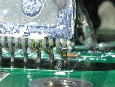
5. Schematics will be very helpful. 6. Check inductors and transformer windings for continuity or resistance. Good luck! |
|
|
Jun 14 2017, 03:21 AM
Show posts by this member only | IPv6 | Post
#388
|
|
Junior Member
6 posts Joined: Jun 2017 |
QUOTE(MichalD @ Jun 12 2017, 05:48 PM) I am not a profesional electrical enegineer but in basic i can recommend you to do following steps. i tested all the diode ok work good, for capacitors i can't test all off them because my tester dont work if i dont disconnect at least on pin to mesure. i dont want to unsolder all caps !Good luck! i tested the biggest ones ok and the small who was suspicious in this thread thanks i get some improvements after replacing fews stuff on psu board : C205 C206 and the broken 0 ohms beetween the to big primary capacitor. Now i get sound quite audible ( fews watts ) but not the fully 150 watts for sure !!! both speaker works ( tremble and boomer ) sound is correct but with some low hummm and white noise. i checked on psu the votalge between big output wire CD+ and CD- (audio board connected ) and i have only 8v is it normal ? i was waiting to get something like 24 volts... i have to investigate in this side. also checked the 3 LM78XX i get 27v on ( lm7824 ) and 12v 10v on the 2 others ---> i need to read and check the ref to see the normal output voltage for these one thanks for your help |
|
|
Jun 14 2017, 03:32 PM
|
|
Junior Member
104 posts Joined: Feb 2017 |
QUOTE(drepou @ Jun 13 2017, 08:21 PM) i tested all the diode ok work good,... For the S750 PSU board are the thick conductors -24 and +24V and more than 80 V without load (with load-amp boards connected is around 65V)Check the markings for voltage regulators (L or LM7XXX) google it for output voltage and measure input voltage and output voltage directly on the input and output pins. 27V for 7824 is a lot, there must be something close to 24V. 8V is very low to power up the amp. |
|
|
Jun 15 2017, 12:45 AM
Show posts by this member only | IPv6 | Post
#390
|
|
Junior Member
6 posts Joined: Jun 2017 |
QUOTE(MichalD @ Jun 14 2017, 08:32 AM) For the S750 PSU board are the thick conductors -24 and +24V and more than 80 V without load (with load-amp boards connected is around 65V) It's was not a good idea to disconnect the CD- and CD+ conductor from psu to audio for checking voltage ! by doing that the sytem is now not working any more even red light stop it after 1 sec ... reconnection of wire but same things .... :-( back to ground zero....Check the markings for voltage regulators (L or LM7XXX) google it for output voltage and measure input voltage and output voltage directly on the input and output pins. 27V for 7824 is a lot, there must be something close to 24V. 8V is very low to power up the amp. |
|
|
Jun 15 2017, 05:51 AM
|
|
Junior Member
104 posts Joined: Feb 2017 |
QUOTE(drepou @ Jun 14 2017, 05:45 PM) It's was not a good idea... Hmmm, that's weird. In S750 i can connect and disconnet at any time and nothing wrong was happened. Check the diodes again, and power mosfets with diode checking or continuity mode. Does have your circuit TOP243 or similiar? I had one PSU board where was faulty TOP243 and a faulty diode powering it. During this fauilure the PSU board does absolutely nothing, no transformer buzzing, no LED light on, no nothing. After replacing diode and TOP243 everything was working like new even with old capacitors. |
|
|
Jun 15 2017, 06:43 AM
Show posts by this member only | IPv6 | Post
#392
|
|
Junior Member
6 posts Joined: Jun 2017 |
yes i have a TOP243Y i was thinking it was working because before the led was green and relay was working but not now.
I will order a new one but i just want dont miss something else and burn the new one. Nice advice MichalD i checked today D9 close from the top243 now she is shorted !! i get 0v when reading backward... she was ok before. i also noted some Strange behaviour on the 4 diode who are close from CD+ CD- some of they give me strange value connected... like 0,2 on conductive way and 0 for other diode reverse way... Strange i will unsolder to confirm 
I also noted i thinks issue with Q17 Q18 Q35 Q34 i get the 0,6 on one direction but also when i reverse the multimeter pins... 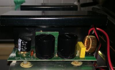
This post has been edited by drepou: Jun 16 2017, 03:56 AM |
|
|
Jun 16 2017, 03:55 AM
|
|
Junior Member
104 posts Joined: Feb 2017 |
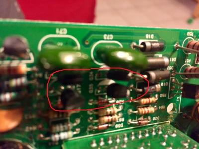
QUOTE(drepou @ Jun 14 2017, 11:43 PM) yes i have a TOP243Y... Chek this PSU scheme for S750 if the TOP243Y part is the same in your PSU and check parts around your TOP243Y specially diodes and find your diode "D9" by following the PCB traces and check it.Attached thumbnail(s) 
|
|
|
|
|
|
Jun 16 2017, 03:57 AM
Show posts by this member only | IPv6 | Post
#394
|
|
Junior Member
6 posts Joined: Jun 2017 |
QUOTE(MichalD @ Jun 15 2017, 08:55 PM) i just modified my previous post yes d9 is dead and somes fews others diode and transistor also now diodes checked in fact seem to be correct if checked unsoldered... now i have to unsolder the transistor to check it it's a real pain to be oblige to desolder to check !and woooo your 2Mohms R8 was not connected too C6 33uf anymore the trace is cut Under the Condo seem to have already huge repair in this area ! This post has been edited by drepou: Jun 18 2017, 12:51 AM |
|
|
Jul 15 2017, 09:14 PM
Show posts by this member only | IPv6 | Post
#395
|
|
Junior Member
6 posts Joined: Jun 2017 |
hello again i changed the top243 but issue is the same i have only 8,8V on CD+ CD- even if i disconnect the wires going to audio board.
( i disconnected only the CD+ and CD- wire ) power on work, led is green, i get huge noise ( kind of hum on satellite speaker ). I dont know what to do now without schematic is not easy other note there is 2 100ohms resitors connected to CD+ it's seem that the other side of the resitor is grounded ?? ( bip with the black wire connected to the big aluminium rad where is screwed the psu board. ) is is normal ? if it's the case with 80v it will be a waste of 800ma in this resitor so p=UxI --> 64 watts bye bye the resistor or this is not the groud.... or it's mean what the big rad is not grounded and is used to send power ??? This post has been edited by drepou: Jul 15 2017, 10:13 PM |
|
|
Jul 18 2017, 07:39 PM
Show posts by this member only | IPv6 | Post
#396
|
|
Newbie
1 posts Joined: Jul 2017 |
Hi,
 By any chance do you know this fault, the Sub light is steady so it is not the same fault again. could this be something stupid like the bass speaker cables come off when I pulled the boards out. I suppose that I could just look, but maybe you know this fault and can help. regards and thanks in advance  smudge |
|
|
Sep 14 2017, 09:30 AM
|
|
Newbie
4 posts Joined: Oct 2009 |
Hi guys, I own a Gigaworks S750 speakers set too. Despite trying so many times I'm not able to get hold of Lex. Does anyone here knows where I can get this fixed? I have no idea what is the actual problem. Probably same as others experienced here. I have never opened it before to check the components. Please do message me if you know someone who is knowledgeable to fix it
|
|
|
Sep 14 2017, 06:34 PM
|
|
Junior Member
104 posts Joined: Feb 2017 |
QUOTE(drepou @ Jul 15 2017, 02:14 PM) hello again i changed the top243 but issue is the same i have only 8,8V on CD+ CD- even if i disconnect the wires going to audio board... Hello, i wasn't here long time because of lot of work and huge fixing for all my other sets of S750. Now i am finishing preparing for much improved heatsink for PSU boards.Without the schematics it is very hard to find the problem. For the resistors i don't know if it is normal. In S750 PSU is grounded only heatsink cooling mosfets. But there is no electrical conductive connection between mosfets and heatsink. The other heatsink for diodes and V.REGs is connected to positive 70V rails thru two capacitors each rail and common inductor. There is no other connection to heatsink so i don't know the purpose of this connection. The other heatsink is connected to positive wave of grid powerline after diode bridge and one D9 if i am right. And now i remember i've touched it with bare hand during operation to check the temperature Attached thumbnail(s) 
|
|
|
Sep 14 2017, 06:38 PM
|
|
Junior Member
104 posts Joined: Feb 2017 |
QUOTE(smudge827 @ Jul 18 2017, 12:39 PM) Hi, Check the area around the big 1000uF capacitor, small yellow one and SMDs around on both AMP boards. Look for the burned or cracked components. Do you removed all degraded glue from the PSU, AMPs and audio processing boards? By any chance do you know this fault, the Sub light is steady so it is not the same fault again. could this be something stupid like the bass speaker cables come off when I pulled the boards out. I suppose that I could just look, but maybe you know this fault and can help. regards and thanks in advance smudge |
|
|
Sep 17 2017, 01:42 AM
|
|
Newbie
2 posts Joined: Jul 2015 |
|
| Change to: |  0.0343sec 0.0343sec
 1.17 1.17
 6 queries 6 queries
 GZIP Disabled GZIP Disabled
Time is now: 14th December 2025 - 02:42 PM |
 Quote
Quote