Welcome Guest ( Log In | Register )

97 Pages « < 81 82 83 84 85 > » Bottom

Outline · [ Standard ] · Linear+

 Repraps and DIY 3D Printing!, Open source hardware~

views
     
altan
post Mar 26 2016, 04:57 PM

Getting Started
**
Junior Member
188 posts

Joined: Sep 2009
From: Either PJ, JB or SG but not at your house!


QUOTE(izzudinhafiz @ Mar 26 2016, 04:43 PM)
CNC mills have this problem too biggrin.gif solution. counterweight http://millhillsupplies.co.uk/wp-content/u.../CNCproj6b1.jpg

of course not as feasible in a 3d printer
*
I always thought of a counter weight system for the Z-axis, I wonder if it actually works or its just for show... sweat.gif
izzudinhafiz
post Mar 27 2016, 06:39 AM

New Member
*
Junior Member
39 posts

Joined: Jun 2013


QUOTE(altan @ Mar 26 2016, 04:57 PM)
I always thought of a counter weight system for the Z-axis, I wonder if it actually works or its just for show... sweat.gif
*
the counterweight for milling machine runs double function. It helps with actuating force. The motor has to move less effective weight, cause the counterweight is partially pulling on the Z axis.

The other is that it prevents sagging of the Z-axis head. The Z-axis can sag by a few thousands of an inch unsupported. You get less sagging with counterweight. It doesnt do anything during a cut, because the Z-axis will be pushed up. But you can minimize the distance from lowest Z-axis "sag" to the highest z-axis "pushed up". I dont know if i made that clear?

It does work extremely well in reducing actuating force but accuracy doesnt really improve. You need rigidity for accuracy (or more aptly, consistency). Different cutting geometry will force the Z-axis different ways and only rigidity can help that.

As for applying it to a 3D printer, actuating force doesnt really bother us too much does it? although, it may help with backlash issues maybe?

This post has been edited by izzudinhafiz: Mar 27 2016, 06:41 AM
caduser
post Mar 27 2016, 07:47 PM

New Member
*
Junior Member
19 posts

Joined: Apr 2006
From: kl


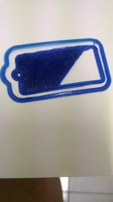
Kenapa 1st layer macam ini


Attached thumbnail(s)
Attached Image
izzudinhafiz
post Mar 27 2016, 07:57 PM

New Member
*
Junior Member
39 posts

Joined: Jun 2013


QUOTE(caduser @ Mar 27 2016, 07:47 PM)
Kenapa 1st layer macam ini
*
Z-axis dekat sangat dengan print bed. cuba naikkan z-axis by 0.1mm dan set height itu sebagai zero (command G92 Z0)

This post has been edited by izzudinhafiz: Mar 27 2016, 07:59 PM
Prosperer
post Mar 27 2016, 11:02 PM

New Member
*
Newbie
0 posts

Joined: Feb 2015
user posted image

user posted image

Currently my problem only leave that much right now and i think it because the lead screw maybe confused.gif
i noticed that other area didn't appeared any artifacts from any axis movement and i print 2 of these "neko" and both happened almost at the same area.

So im still in bruce.gif moods to find the source for the problem

edit
im printing with 60mm/s

This post has been edited by Prosperer: Mar 27 2016, 11:04 PM
izzudinhafiz
post Mar 27 2016, 11:47 PM

New Member
*
Junior Member
39 posts

Joined: Jun 2013


QUOTE(Prosperer @ Mar 27 2016, 11:02 PM)
user posted image

user posted image

Currently my problem only leave that much right now and i think it because the lead screw maybe confused.gif
i noticed that other area didn't appeared any artifacts from any axis movement and i print 2 of these "neko" and both happened almost at the same area.

So im still in bruce.gif moods to find the source for the problem

edit
im printing with 60mm/s
*
can upload a higher res image? cant see the problem. so pixelated biggrin.gif
Prosperer
post Mar 28 2016, 12:17 AM

New Member
*
Newbie
0 posts

Joined: Feb 2015
QUOTE(izzudinhafiz @ Mar 27 2016, 11:47 PM)
can upload a higher res image? cant see the problem. so pixelated biggrin.gif
*
user posted image
user posted image

i hope this will do it biggrin.gif
izzudinhafiz
post Mar 28 2016, 12:38 AM

New Member
*
Junior Member
39 posts

Joined: Jun 2013


QUOTE(Prosperer @ Mar 28 2016, 12:17 AM)
user posted image
user posted image

i hope this will do it biggrin.gif
*
vertical banding(ringing) or the horizontal banding one?

This post has been edited by izzudinhafiz: Mar 28 2016, 12:39 AM
Prosperer
post Mar 28 2016, 01:01 AM

New Member
*
Newbie
0 posts

Joined: Feb 2015
QUOTE(izzudinhafiz @ Mar 28 2016, 12:38 AM)
vertical banding(ringing) or the horizontal banding one?
*
the horizontal one
edit
and i think the vertical one is cause by slicer maybe confused.gif cause it didnt make smooth round around the outer shell, it more like zigzag (sorry i dont know how to describe it)

This post has been edited by Prosperer: Mar 28 2016, 01:05 AM
izzudinhafiz
post Mar 28 2016, 02:14 AM

New Member
*
Junior Member
39 posts

Joined: Jun 2013


QUOTE(Prosperer @ Mar 28 2016, 01:01 AM)
the horizontal one
edit
and i think the vertical one is cause by slicer maybe confused.gif  cause it didnt make smooth round around the outer shell, it more like zigzag (sorry i dont know how to describe it)
*
last fix u can do to reduce the vertical banding is to remove the spring beneath the heated bed. replace it with nuts and washers so that its stiff. It improved my prints dramatically. CAUTION: head crash can be devastating!

As for the horizontal banding. Err. I dont know how else to improve print quality. one test you can do is to increase/decrease your step/mm for the z-axis slightly. 1 - 2 % and see if the banding moves or reduce. If it does you can confirm that there is inaccuracy in the Z-axis height. Caused by: Backlash (unlikely), vibration and wobble (more likely) or simply wrong step/mm for the z axis.

If changing step/mm doesnt affect the banding at all. Its safe to conclude that the problem DOES NOT lie in the Z-axis and may come from elsewhere. Inconsistent pressure in the hotend, slicer error or too high of a printing speed.
Prosperer
post Mar 28 2016, 10:33 AM

New Member
*
Newbie
0 posts

Joined: Feb 2015
QUOTE(izzudinhafiz @ Mar 28 2016, 02:14 AM)
last fix u can do to reduce the vertical banding is to remove the spring beneath the heated bed. replace it with nuts and washers so that its stiff. It improved my prints dramatically. CAUTION: head crash can be devastating!

As for the horizontal banding. Err. I dont know how else to improve print quality. one test you can do is to increase/decrease your step/mm for the z-axis slightly. 1 - 2 % and see if the banding moves or reduce. If it does you can confirm that there is inaccuracy in the Z-axis height. Caused by: Backlash (unlikely), vibration and wobble (more likely) or simply wrong step/mm for the z axis.

If changing step/mm doesnt affect the banding at all. Its safe to conclude that the problem DOES NOT lie in the Z-axis and may come from elsewhere. Inconsistent pressure in the hotend, slicer error or too high of a printing speed.
*
I didnt use any spring on my bed, is this too high for z axis 5086 s/mm before it only at 2579s/mm and after i change my stepstick the s/mm also change.


izzudinhafiz
post Mar 28 2016, 10:53 AM

New Member
*
Junior Member
39 posts

Joined: Jun 2013


QUOTE(Prosperer @ Mar 28 2016, 10:33 AM)
I didnt use any spring on my bed, is this too high for z axis 5086 s/mm before it only at 2579s/mm and after i change my stepstick the s/mm also change.
*
isnt 5086 too low? im assuming u're using a 8mm leadscrew. That and the DRV8825 driver can do 1/32 microstepping. Should give you 5120 step/mm.

unlike the other belt driven axis, leadscrew arent suppose to be affected by hysteresis. so using the mathematical value of 5120 should be prefered. Then if the z-axis fail to move by the desired amount, you should troubleshoot the cause for it. Mainly backlash is the cause.
Prosperer
post Mar 28 2016, 10:58 AM

New Member
*
Newbie
0 posts

Joined: Feb 2015
QUOTE(izzudinhafiz @ Mar 28 2016, 10:53 AM)
isnt 5086 too low? im assuming u're using a 8mm leadscrew. That and the DRV8825 driver can do 1/32 microstepping. Should give you 5120 step/mm.

unlike the other belt driven axis, leadscrew arent suppose to be affected by hysteresis. so using the mathematical value of 5120 should be prefered. Then if the z-axis fail to move by the desired amount, you should troubleshoot the cause for it. Mainly backlash is the cause.
*
I dont know, i just adjust it cause when i print 10mm height cube it gave me 10.4mm so i adjust it and now i i can get 10mm if i ask for 10mm on all side.
Should i adjust it?
Drian
post Mar 28 2016, 11:00 AM

Look at all my stars!!
*******
Senior Member
4,999 posts

Joined: Jan 2003


QUOTE(Prosperer @ Mar 28 2016, 12:17 AM)
user posted image
user posted image

i hope this will do it biggrin.gif
*
What is your Z resolution without microstep?

It looks like your layer height is not in multiples of your Z resolution without microstep. Do you know your lead screw specs?


Don't rely on microsteps for your resolution, the stepper will likely skip because the torque in microstep mode is way lower than the normal mode. At 1/16 microstep the torque is only 10% of your motors rated torque.

http://www.micromo.com/microstepping-myths-and-realities

The consequence is that if the load torque plus the motor’s friction and detent torque is greater than the incremental torque of a microstep successive microsteps will have to be realized until the accumulated torque exceeds the load torque plus the motor’s friction and detent torque.

Simply stated, taking a microstep does not mean the motor will actually move! And if reversing direction is desired a whopping number of microsteps may be needed before movement occurs. That’s because the motor shaft torque must be decremented from whatever positive value it has to a negative value that will have sufficient torque to cause motion in the negative direction.


This post has been edited by Drian: Mar 28 2016, 11:04 AM
Prosperer
post Mar 28 2016, 11:22 AM

New Member
*
Newbie
0 posts

Joined: Feb 2015
QUOTE(Drian @ Mar 28 2016, 11:00 AM)
What is your Z resolution without microstep?

It looks like your layer height is not in multiples of your Z resolution without microstep. Do you know your lead screw specs?
Don't rely on microsteps for your resolution, the stepper will likely skip because the torque in microstep mode is way lower than the normal mode. At 1/16 microstep the torque is only 10% of your motors rated torque.

http://www.micromo.com/microstepping-myths-and-realities

The consequence is that if the load torque plus the motor’s friction and detent torque is greater than the incremental torque of a microstep successive microsteps will have to be realized until the accumulated torque exceeds the load torque plus the motor’s friction and detent torque.

Simply stated, taking a microstep does not mean the motor will actually move!  And if reversing direction is desired a whopping number of microsteps may be needed before movement occurs.  That’s because the motor shaft torque must be decremented from whatever positive value it has to a negative value that will have sufficient torque to cause motion in the negative direction.

*
im printing in 0.2 layer height and according to prusa calculator i can print between 0.19375, 0.2 and 0.20625000000000002
i think my lead screw got 1mm pitch
Drian
post Mar 28 2016, 11:37 AM

Look at all my stars!!
*******
Senior Member
4,999 posts

Joined: Jan 2003


QUOTE(Prosperer @ Mar 28 2016, 11:22 AM)
im printing in 0.2 layer height and according to prusa calculator i can print between 0.19375, 0.2 and 0.20625000000000002
i think my lead screw got 1mm pitch
*
Can you check how many mm it moves forward/backwards for every 1 rotation. Usually it is 2mm,4mm,8mm standard for leadscrew.
The way leadscrew is calculated is not only using pitch but also "number of starts"

http://www.protoparadigm.com/news-updates/...in-3d-printers/
QUOTE
The lead is the distance that will be traveled in the course of one revolution of the leadscrew. In the case of a single-start screw, the lead is the same as the pitch.

10 threads per inch is a 1/10 inch pitch, which means one rotation takes you 1/10 inches

For a multi-start screw, the lead is the pitch multiplied by the number of starts.
for eg:- this is 8mm
http://www.aliexpress.com/item/RepRap-3D-P...99-dfa7b0d9ae1a

this one is 4mm
http://www.aliexpress.com/item/3D-Printer-...1a-2c1a64604dea
Drian
post Mar 28 2016, 11:46 AM

Look at all my stars!!
*******
Senior Member
4,999 posts

Joined: Jan 2003


QUOTE(Prosperer @ Mar 28 2016, 11:22 AM)
im printing in 0.2 layer height and according to prusa calculator i can print between 0.19375, 0.2 and 0.20625000000000002
i think my lead screw got 1mm pitch
*
Actually how you get your steps/mm?


Drian
post Mar 28 2016, 11:50 AM

Look at all my stars!!
*******
Senior Member
4,999 posts

Joined: Jan 2003


QUOTE(Prosperer @ Mar 28 2016, 11:22 AM)
im printing in 0.2 layer height and according to prusa calculator i can print between 0.19375, 0.2 and 0.20625000000000002
i think my lead screw got 1mm pitch
*
just ignore my question above ..haha I realised you will always get multiples of your resolution for 0.2mm layer height regardless of 2mm,4mm or 8mm lead screw.


Drian
post Mar 28 2016, 12:02 PM

Look at all my stars!!
*******
Senior Member
4,999 posts

Joined: Jan 2003


QUOTE(Prosperer @ Mar 28 2016, 10:33 AM)
I didnt use any spring on my bed, is this too high for z axis 5086 s/mm before it only at 2579s/mm and after i change my stepstick the s/mm also change.
*
Your steps/mm seems off.

if your using 2mm lead, 1.8 degree stepper

it should be

1/16 ustep, 1600s/mm
1/32 ustep, 3200s/mm
1/8 ustep, 800s/mm


even if you are using 1mm lead , the 5086 steps/mm seems a little bit off.


Prosperer
post Mar 28 2016, 12:05 PM

New Member
*
Newbie
0 posts

Joined: Feb 2015
QUOTE(Drian @ Mar 28 2016, 12:02 PM)
Your steps/mm seems off.

if your using 2mm lead, 1.8 degree stepper

it should be

1/16 ustep, 1600s/mm
1/32 ustep, 3200s/mm
1/8  ustep,  800s/mm
even if you are using 1mm lead , the 5086 steps/mm seems a little bit off.
*
thank you, i'll try the number that you and izzudinhafiz give me and check it from there, and sorry it my mistake actually i using threaded rods on my prusa not lead screw

97 Pages « < 81 82 83 84 85 > » Top
 

Change to:
| Lo-Fi Version
0.0334sec    0.37    6 queries    GZIP Disabled
Time is now: 29th November 2025 - 05:31 AM