Welcome Guest ( Log In | Register )

Bump Topic Topic Closed RSS Feed
19 Pages « < 13 14 15 16 17 > » Bottom

Outline · [ Standard ] · Linear+

DIY T-Amp user/diyer come here :), TA2024 complete build board diy

views
     
ongbs
post Sep 23 2008, 11:17 AM

Who am I ?
******
Senior Member
1,083 posts

Joined: Sep 2004
QUOTE(Y.C. @ Sep 23 2008, 11:08 AM)
I am also in this category too.  laugh.gif

Jazzy, yes, I shall start mine after receiving my new boards from Xtorm and would post my report from time to time.
I just hope and pray hard that I don't damage the board and that shall be end of report sooner than expected.  sweat.gif

Happy tweaking, folks.  thumbup.gif
*
Since we are putting discrete "through hole" component over SMD PCB copper pad, after soldered DON'T press the components too hard as this will damage the solder pad..."tercabut" doh.gif
ongbs
post Sep 23 2008, 02:03 PM

Who am I ?
******
Senior Member
1,083 posts

Joined: Sep 2004
Y.C,

Don't worry as we have the full circuit design....
Even with some tracks broken still able to jump wires to correct points.
Unless the TA2024 kong...that is "total loss" tongue.gif
ongbs
post Sep 23 2008, 02:54 PM

Who am I ?
******
Senior Member
1,083 posts

Joined: Sep 2004
QUOTE(jazzy939 @ Sep 23 2008, 02:43 PM)
onbs,
My thoughts exactly!  thumbup.gif I'm impressed biggrin.gif
Keep up the good work eh! wink.gif
*
"onbs," jangan lah bro...ongbs lah.. doh.gif (jk)
My ear "taklak mali", but my eyes still sharp...hehe whistling.gif

Y.C,
Just remember when you work on solder, try to keep a safe distance with TA chip (the pins).
Once you accidentally solder/short the IC leads...it is difficult to de-solder them "clean and safe" sweat.gif

This is true for all new comers with soldering works, because the PCB tracks around IC leads is the weakest parts! (very very thin) sad.gif

This post has been edited by ongbs: Sep 23 2008, 02:54 PM
ongbs
post Sep 23 2008, 08:23 PM

Who am I ?
******
Senior Member
1,083 posts

Joined: Sep 2004
Wah...how come today all playing 'gun" not Amp huh? doh.gif tongue.gif

xtorm, do something...hardly see your report now sad.gif


Added on September 23, 2008, 8:29 pm
QUOTE(jazzy939 @ Sep 23 2008, 03:23 PM)
alamak sorry bro.. typo lah!  laugh.gif

ongbs, may be you can also publish some DO's and DONT's when upgrading the T-Amp? How about that? wink.gif

Glad that you also noticed that!  thumbup.gif
*
bro jazzy...no need lah....
If i post pic of my "handsome" soldering works for sure all will shakehead.gif shakehead.gif shakehead.gif and run away laugh.gif
In your links, plenty of info can read and learn smile.gif

I learned soldering many years back...damaged many PCB/components even devices sad.gif
A hard way coz that time internet still not popular, the only way to improve is via practice, practice...and practice sweat.gif

This post has been edited by ongbs: Sep 23 2008, 08:33 PM
ongbs
post Sep 23 2008, 10:34 PM

Who am I ?
******
Senior Member
1,083 posts

Joined: Sep 2004
QUOTE(Y.C. @ Sep 23 2008, 09:04 PM)
Hey, you guys are not helping me at all and if anything scaring the xxxx out of me.   cry.gif 

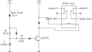
Since I have bought almost the entire discreet components needed, perhaps I should source for an empty board with though holes to mount them with point to point wiring instead. And last, transfer the TA2024 chip over.  drool.gif
*
Walau Y.C...if you can "transplant" the TA2024 chip that mean you already "graduated" liau tongue.gif
You try to find a faulty computer SDRAM/DDR board, remove the memory chip and put it back,
without shorting the leads nor damage the solder pads....see how it go brows.gif


Added on September 23, 2008, 10:41 pm
QUOTE(ijan @ Sep 23 2008, 08:35 PM)
Aiyo, dun malu2 la bro ongbs, soldering is sumthing you haf to learn by practice, no matter how much reading, learning theories and BS u go through, doing the darn soldering itself teaches you the whole bunch about it. But not adviseable to practice soldering on ur TAMP board, try cari old rosak PCB, or old computer psu.
*
hehe, PC parts is easier to find and "tough" to master...mostly multi-layer and SMD sweat.gif
But still most of the IC is hard to touch as the leads/pins clearance too small nowadays....


Added on September 23, 2008, 10:43 pm
QUOTE(grandspy @ Sep 23 2008, 10:16 PM)
xtorm, when is the latest shipment going to come in? My hands are getting real itchy.

BTW, should I get a new soldering iron or should I just 'revive' my 15 year old Antex?
What type of solder do you use? Audiophile grade solder (if there's such a thing) that makes the sound more 'definitive'?  brows.gif
Where do you get the SMPS?
*
I think such a high grade solder leads do exist, just not sure will we able to find locally.
Expect a "bomb" for its cost sweat.gif

This post has been edited by ongbs: Sep 23 2008, 10:43 PM
ongbs
post Sep 23 2008, 11:24 PM

Who am I ?
******
Senior Member
1,083 posts

Joined: Sep 2004
Y.C,

try get TA2020 or 2022, they are easier to work on smile.gif
ongbs
post Sep 24 2008, 12:17 AM

Who am I ?
******
Senior Member
1,083 posts

Joined: Sep 2004
QUOTE(jazzy939 @ Sep 24 2008, 12:00 AM)
Y.C.,
Yes.. I saw that already. You were editing it while I was composing the reply.
I might consider it too..
But I got one good circuit from that site, the 'anti-thump' relay circuit. Chances are I will be making that circuit..
Anyone interested in building that circuit? tongue.gif
*
Jazzy you mean this?


Attached image(s)
Attached Image
ongbs
post Sep 24 2008, 12:34 AM

Who am I ?
******
Senior Member
1,083 posts

Joined: Sep 2004
QUOTE(jazzy939 @ Sep 24 2008, 12:19 AM)
ongbs,
Nope.. that's to adjust the DC offset. But according to the text, it does not solve the 'thump' problem.. tongue.gif
It's the other circuit with a relay... wink.gif
*
hehe simple circuit...kasi try lah...then no more "thumb" up tongue.gif

add on:
aiya...sad news sad.gif


This post has been edited by ongbs: Sep 24 2008, 12:40 AM
ongbs
post Sep 24 2008, 12:41 AM

Who am I ?
******
Senior Member
1,083 posts

Joined: Sep 2004
must be this one then: icon_rolleyes.gif


Attached thumbnail(s)
Attached Image
ongbs
post Sep 24 2008, 12:44 AM

Who am I ?
******
Senior Member
1,083 posts

Joined: Sep 2004
QUOTE(jazzy939 @ Sep 24 2008, 12:42 AM)
yeah.. thats the one dude! wink.gif
*
replace R1 to variable preset then you can adj the delay timing smile.gif
ongbs
post Sep 24 2008, 01:09 AM

Who am I ?
******
Senior Member
1,083 posts

Joined: Sep 2004
QUOTE(jazzy939 @ Sep 24 2008, 12:51 AM)
or change the capacitor as the timing is the time taken to charge the cap.. either way, it's your choice! biggrin.gif
*
fast fast kasi test lah...feel "horny" coz not many pics lately doh.gif
ongbs
post Sep 24 2008, 02:12 AM

Who am I ?
******
Senior Member
1,083 posts

Joined: Sep 2004
QUOTE(jazzy939 @ Sep 24 2008, 01:25 AM)
Hmm.. not so good news la bro ongbs,

the circuit managed to prevent the power on thump as it takes about 4 secs. to energize the relay but unable to remove the power off thump as it took 2 secs. for the relay to de-energized.

Although I do not have issues with power off thumps, but I don't think the circuit is good enough for my baby..

I have other speaker protection relay circuit which I intend to do probably this weekend.. tongue.gif Will update the thread if necessary.

I also found there is a Speaker Protection KIT sold by NIXIE at a price of... ready or not: RM80!
Cheap considering you're protecting a set of expensive speakers.. too much is compared to the cost of the basic T-Amp! ...tongue.gif

It's your call!  whistling.gif
*
bro jazzy,

The delay off 2s should be caused by your powerful mod "power caps".
Refer to my edited pic, your current Power Switch should have more than 1 contact right?

Try connect the wire at SW2 position to the relay (+ve) via another normally open contact (N/O of power switch) should solve your problem.

You get what I mean bro? Try lah...

After this mod the relay will cutoff immediately once you turn of T-amp power switch (not your main 13A socket switch).
Let me know if you can't get what I mean, I will try to explain more smile.gif

This post has been edited by ongbs: Sep 24 2008, 02:18 AM


Attached thumbnail(s)
Attached Image
ongbs
post Sep 24 2008, 02:25 AM

Who am I ?
******
Senior Member
1,083 posts

Joined: Sep 2004
bro jazzy, here is the connection pic of the power switch.
Sorry for my "handsome" hand draft pic tongue.gif


Attached thumbnail(s)
Attached Image
ongbs
post Sep 24 2008, 03:19 AM

Who am I ?
******
Senior Member
1,083 posts

Joined: Sep 2004
QUOTE(jazzy939 @ Sep 24 2008, 02:56 AM)
bro ongbs,
I got you loud and clear there! thumbup.gif
I like the way you think 'outside' the box... wink.gif
Ok will consider that against my existing circuit.. will put that up by this weekend.
That circuit come from another power amp which I have built. a discrete 40W+40W that can actually give the T-Amp a run for it's money.. it is 'cheap' costing almost the same price like the T-Amp.. I nicknamed it D'Bomb, which I was discussing losely with gabanyayaya some postings back..
The main advantage of this circuit is of it's low component count!
Now.. if i were to package this in a kit form(anti-thumping kit for T-Amps) and put it for sale on ebay....  hmm.gif

p/s: If you see my earlier posted pix of my casing, there is no inclusion of a power switch. It has an IEC socket. Power switch comes from the mains socket switch! Talk about minimalisation! tongue.gif

Another KIC (Keep It Cheap) approach is to use a simple DPST switch. ON speaker switch AFTER power ON, OFF speaker switch BEFORE power OFF!  icon_idea.gif
*
Oh...you power switch located outside, forgot liau doh.gif
Still able to do it with another extra simple relay (replace the SW2 N/O contact).....interested? brows.gif

This circuit is very simple beside low components count. thumbup.gif

"Another KIC (Keep It Cheap) approach is to use a simple DPST switch. ON speaker switch AFTER power ON, OFF speaker switch BEFORE power OFF!"==> this one a bit leceh leh hmm.gif

This post has been edited by ongbs: Sep 24 2008, 03:20 AM
ongbs
post Sep 24 2008, 09:07 AM

Who am I ?
******
Senior Member
1,083 posts

Joined: Sep 2004
QUOTE(jazzy939 @ Sep 24 2008, 08:45 AM)
ongbs,
Currently my practise is that I would manually plug out each of the speaker cables before switching off and replug them back moments after power on.
Leceh, yes.. better than having this uncomfortable feeling hearing the 'thumb' sound coming from my speakers..
Installing a switch (KIC)for this is a whole lot better than manual plug/unplug. Having a protection circuit is obviously convenient...if you got the RMXX, why not!  biggrin.gif

Another simple circuit would be employing the 555 timer(and control relay) for this purpose, and using the same SW2 N/O contact arrangement like you proposed.
Have to check the cost vs simplicity. Then later will decide.. wink.gif

On another subject matter,
Someone PMed me and say this thread is slowing down a lot. No more interesting mod/work/pictures..
I guess seeing the number of views against the postings roughly we have about 10 views per posting.
There are not many active posters here so, you know where the views are coming from...  tongue.gif
*
hmm what to do, out of >30 T-amp owners only less than 10 are active sad.gif

OK keep us inform about your anti-thumb progress smile.gif

This post has been edited by ongbs: Sep 24 2008, 09:11 AM
ongbs
post Sep 24 2008, 11:38 AM

Who am I ?
******
Senior Member
1,083 posts

Joined: Sep 2004
QUOTE(jazzy939 @ Sep 24 2008, 11:20 AM)
I think so too!
555 timer should be known by everyone in the electronic hobbyist world..
Not to worry, there are abundance in the net. I have a collection too! biggrin.gif
Your T-Amp should be arriving.. this week?  hmm.gif
*
bro,

You might face power off thumb problem even with this 555 timer coz the power caps hold amble of power that may "hold" the relay in ON state for a few sec after the main power cutoff.
You need to tweak this circuit a little bit. smile.gif
ongbs
post Sep 24 2008, 01:55 PM

Who am I ?
******
Senior Member
1,083 posts

Joined: Sep 2004
QUOTE(wui223 @ Sep 24 2008, 01:49 PM)
Guys, i just realized the Tripath website is closed. Anyone have a copy of TA2024 datasheet? and also the schematic of our T-amp board?
*
Bro, it is located in the 1st page of this thread. blush.gif
ongbs
post Sep 24 2008, 01:57 PM

Who am I ?
******
Senior Member
1,083 posts

Joined: Sep 2004
QUOTE(Y.C. @ Sep 24 2008, 01:17 PM)
Ekool,
Our T-amp is as tiny as size of mykad, its design simple using SMDs instead of discreet components and essentially a plug and play item. Our sifus here have replaced most SMDs with discreet components and I shall follow suit soon after I receive my new T-amp boards. I hope to replace even more SMDs if I don’t damage the board prematurely in the process. I did not buy the components below and may pick them up along the way when I perform the mod:-
2 pcs of 100pF Capacitors at location C23,C24
5 pcs of 1000pF Capacitors at location C8,C9,C10,C11,C21
4 pcs of Diodes at location D5,D6,D7,D8

I shall post photos plus comments before, during and after the SMDs mod; I assume you have a pair of steady hands, game to join me?  brows.gif

If you read through the postings in this thread, you’ll notice that I was on the verge of buying Charlize (TA2020) before I chanced upon this great little gem of ours at only RM55. At this juncture, I’m more than happy with its performance even before the SMDs mod, so I shall give TA2020 a go and move on with life, work, family and usual listening enjoyment. For info of all, the TA2024 chip alone could be bought in PRC for as low as RM6 each piece. And if I were to replace all SMDs including diodes, I mentioned that I might as well use a new through-hole board altogether.
*
Walau bro..."if I don’t damage the board prematurely in the process" ==> cheer up and let's have some funs!

Why need to replace Diodes? Got C21 meh? sweat.gif
ongbs
post Sep 24 2008, 02:00 PM

Who am I ?
******
Senior Member
1,083 posts

Joined: Sep 2004
QUOTE(jazzy939 @ Sep 24 2008, 01:58 PM)
wui,
the Evaluation Board schematic is available at the beginning of the thread for download.

The datasheet for TA2024 is from my T-Amp stuffs folder<-- as earlier noticed by our Mr.Spy.. tongue.gif

Here you go! For everyone to d/l too! biggrin.gif
*
wui, you must D/L the evaluation PDF coz it mostly same as our board smile.gif
Last time I didn't know that got this PDF, I spent hours to trace the components sweat.gif doh.gif

This post has been edited by ongbs: Sep 24 2008, 02:01 PM
ongbs
post Sep 24 2008, 07:25 PM

Who am I ?
******
Senior Member
1,083 posts

Joined: Sep 2004
QUOTE(Y.C. @ Sep 24 2008, 03:52 PM)
bro,
Yes, that I will do and will have fun doing the soldering/desoldering work. Thank you.  nod.gif

No, I would not replace the diodes if I stick to our T-amp board unless of course I really go ahead with a new through-hole board.

C21 is located at the positive side of the power supply input according to the Schematic of of the Evaluation Board.
*
I remembered i search C21 before, can't find it on our board hmm.gif

19 Pages « < 13 14 15 16 17 > » Top
Topic ClosedOptions
 

Change to:
| Lo-Fi Version
0.0552sec    0.77    7 queries    GZIP Disabled
Time is now: 12th December 2025 - 02:03 PM