Welcome Guest ( Log In | Register )

33 Pages « < 26 27 28 29 30 > » Bottom

Outline · [ Standard ] · Linear+

PC Audio Creative GigaWorks S750 7.1 speaker repair, A short guide and info with pictures...

views
     
MichalD
post Jan 8 2020, 01:08 AM

Getting Started
**
Junior Member
101 posts

Joined: Feb 2017
QUOTE(STREXNIN100 @ Jan 7 2020, 10:48 AM)
Not. I have a power grid voltage of 220VAC +/- 5% in my mill...
*
OK of course, i understand.

QUOTE(STREXNIN100 @ Jan 7 2020, 10:48 AM)
On Q2 it is more interesting than on Q3 because in this case there will be no influence of the trigger circuit D6, D7 and C54 on the waveform.
*
OK understand.

QUOTE(STREXNIN100 @ Jan 7 2020, 10:48 AM)
Understand how perfect the differential inputs (or external differential probes) of your oscilloscope are, you need to read the documentation for them. Now there is no need to measure waveforms at different points of the device at the same time - just use one channel!
Just in case for the future: please measure with a good tester the resistance between the terminals of your dif. probe. In all four possible options. If the tester shows a short circuit in at least one of the measurement options (or even a resistance of hundreds of kilo-ohms), then these dif. probe cannot simultaneously record oscillograms in different — not having a common point — device locations !! In addition, when measuring in devices with high voltages, you must make sure in the manual that your dif. probe withstand this voltage difference !!
*
My dif. probe has resistance about 10 MOhms between testing red and black plugs. 5 MOhms is the resistance between testing leads and of BNC for oscilloscope input. So it should be safe to measure couple hundreds of V.
The standard passive probes delivered with the oscilloscope has about 9 MOhms on 10x setting. So no problem too.


QUOTE(STREXNIN100 @ Jan 7 2020, 10:48 AM)
The following oscillograms are much more interesting to me now:
1. Between the source (S) Q2 and the anode (G) Q2.
2. Between the source (S) Q2 and the gate (G) Q2.
*
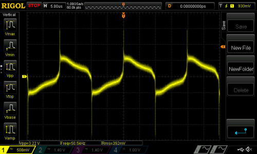
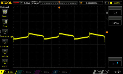
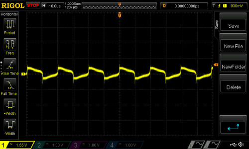
Here are the oscilograms, i was strong enough to try both channels in one screen smile.gif


Look here:

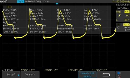
Q2S - AD22 measured with differential probe. 500mV/div, 5us, trigger at 930mV.
user posted image

Q2S - AD22 measured with differential probe. 1,55V/div, 5us, trigger at 930mV.
user posted image

Q2S - AD22 measured with differential probe. 1,55V/div, 10us, trigger at 930mV.
user posted image

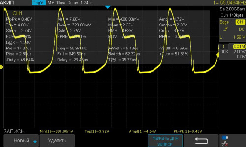
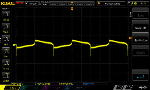
Q2S - AD22 measured with differential probe. 1,4V/div, 5us, trigger at 1.01V. Comparable oscilogram with lower one.
user posted image

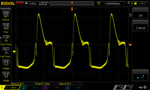
Q2S - Q2G measured with differential probe. 1,4V/div, 5us, trigger at 1.01V. Comparable oscilogram with upper one.
user posted image

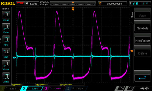
This will happend when measuring both signals (AD22 and Q2G) at once with common ground at Q2S, no matter what side is differential probe used, or diff. probe + passive probe or two passive probes.
user posted image

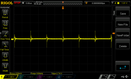
AD22 signal is ruined when try to measure it with passive probe.
user posted image

Hope this oscillograms will help you.
STREXNIN100 P
post Jan 8 2020, 06:05 PM

New Member
*
Probation
33 posts

Joined: Nov 2019


QUOTE(MichalD @ Jan 7 2020, 08:08 PM)
Thanks! I wanted to answer yesterday, but my status here does not allow sending more than three messages a day!
QUOTE
My dif. probe has resistance about 10 MOhms between testing red and black plugs. 5 MOhms is the resistance between testing leads and of BNC for oscilloscope input.
Yes, great probes!
QUOTE
So it should be safe to measure couple hundreds of V.
Yes, I totally agree!
QUOTE
The standard passive probes delivered with the oscilloscope has about 9 MOhms on 10x setting. So no problem too.
Here you are also absolutely right. You have good equipment, and sometimes I have to envy you. smile.gif
QUOTE
Here are the oscilograms, i was strong enough to try both channels in one screen smile.gif
...Q2S - AD22 measured with differential probe.
These three waveforms are good, although the first of them I liked the most and will be useful ...
QUOTE
Q2S - AD22 measured with differential probe. 1,4V/div, 5us, trigger at 1.01V. Comparable oscilogram with lower one.
  .............................
Q2S - Q2G measured with differential probe. 1,4V/div, 5us, trigger at 1.01V. Comparable oscilogram with upper one.
That was a good idea! Although, of course, I would expect them to overlap due to the simultaneous use of channels 1 and 2, as is done on the oscillograms below - if only I understand correctly. In any case, this is what you need, and I can combine them myself without any labor!

I have these very waveforms look a little different ...

Q2S - AD22
user posted image

Q2S - Q2G
user posted image

And your "Q2S - AD22 measured with differential probe. 1,4V / div, 5us, trigger at 1.01V. Comparable oscilogram with lower one." The waveform surprises me. It seems she should not be like that ...

QUOTE
This will happend when measuring both signals (AD22 and Q2G) at once with common ground at Q2S, no matter what side is differential probe used, or diff. probe + passive probe or two passive probes.
Yes, here you are absolutely right - if I understood the translation from Google correctly. smile.gif And you have beautifully good oscillograms in a two-channel version!
But, perhaps, the blue waveform is not connected to the AD22 point on the board, because Q2S - Q2G and Q2S - AD22 should theoretically practically coincide in shape, and should come closer to the red graph in shape!
QUOTE
AD22 signal is ruined when try to measure it with passive probe.
It seems to me that here, like the blue line in the graph above (if you look at your last message), this is not the AD22 point on the board, but the Q2S point taken by mistake! Therefore, these oscillograms look like a straight line with spurious bursts at the moment of switching the MOSFET.
And one more thing: it’s a little wrong that all the oscillograms were taken with the oscilloscope inputs closed (for alternating voltage). The constant component of the signal, which is not visible in this case, is very important for analyzing the correct operation of semiconductor devices!

Have a nice week !! ))
MichalD
post Jan 9 2020, 08:09 AM

Getting Started
**
Junior Member
101 posts

Joined: Feb 2017
QUOTE(STREXNIN100 @ Jan 8 2020, 11:05 AM)
But, perhaps, the blue waveform is not connected to the AD22 point on the board, because Q2S - Q2G and Q2S - AD22 should theoretically practically coincide in shape, and should come closer to the red graph in shape!
It seems to me that here, like the blue line in the graph above (if you look at your last message), this is not the AD22 point on the board, but the Q2S point taken by mistake! Therefore, these oscillograms look like a straight line with spurious bursts at the moment of switching the MOSFET.
*
Hmmm, not sure but OK i will do re-check of the connections and post the photos during the weekend. I've soldered short leads to measuring points Q2S which is same as T1 1(4), Q2G and AD22.

QUOTE(STREXNIN100 @ Jan 8 2020, 11:05 AM)
And one more thing: it’s a little wrong that all the oscillograms were taken with the oscilloscope inputs closed (for alternating voltage). The constant component of the signal, which is not visible in this case, is very important for analyzing the correct operation of semiconductor devices!
*
Here i am not understand what are you talking about "oscilloscope inputs closed" sad.gif i am still a newbie in oscilloscope measurements and it's features, but i want to learn it all.
STREXNIN100 P
post Jan 10 2020, 04:15 AM

New Member
*
Probation
33 posts

Joined: Nov 2019


QUOTE(MichalD @ Jan 9 2020, 03:09 AM)
Hello, MichalD!
I saw this morning, and understood. Today and tomorrow afternoon I will be busy at work - and I'm sorry that I will not be able to discuss this in detail until tomorrow evening. )) But I want to write to you.
QUOTE
...what are you talking about "oscilloscope inputs closed"...
I will try to write about it by tomorrow evening - or maybe Saturday afternoon. To write in detail, you need to be a little free.
MichalD
post Jan 10 2020, 04:36 AM

Getting Started
**
Junior Member
101 posts

Joined: Feb 2017
QUOTE(STREXNIN100 @ Jan 9 2020, 09:15 PM)
I will try to write about it by tomorrow evening - or maybe Saturday afternoon. To write in detail, you need to be a little free.
*
OK no problem, until the weekend i am not able to make any measurements because i have all "toys" off hand.
STREXNIN100 P
post Jan 11 2020, 05:44 PM

New Member
*
Probation
33 posts

Joined: Nov 2019


QUOTE(MichalD @ Jan 9 2020, 03:09 AM)
...what are you talking about "oscilloscope inputs closed"...
I apologize. I started writing, but now I urgently need to leave before evening, when I can finish this text.
This is an important point when measuring with an oscilloscope, and I have a small request - if it does not bother you at all - not to take new measurements until I send you here what I started!

MichalD
post Jan 11 2020, 05:54 PM

Getting Started
**
Junior Member
101 posts

Joined: Feb 2017
QUOTE(STREXNIN100 @ Jan 11 2020, 10:44 AM)
I apologize. ...
*
Unfortunately my plans was yesterday suddenly changed and i am not back at home this weekend so i have no access to maky any measurements sad.gif
STREXNIN100 P
post Jan 11 2020, 10:09 PM

New Member
*
Probation
33 posts

Joined: Nov 2019


QUOTE(MichalD @ Jan 11 2020, 12:54 PM)
Unfortunately my plans was yesterday suddenly changed...
OK! Then I calmly finishing. ))

MichalD
post Jan 12 2020, 12:47 AM

Getting Started
**
Junior Member
101 posts

Joined: Feb 2017
QUOTE(STREXNIN100 @ Jan 11 2020, 03:09 PM)
OK! Then I calmly finishing. ))
*
OK good luck.
STREXNIN100 P
post Jan 12 2020, 06:04 AM

New Member
*
Probation
33 posts

Joined: Nov 2019


QUOTE(MichalD @ Jan 9 2020, 03:09 AM)
...what are you talking about "oscilloscope inputs closed"...
As a rule, all general-purpose oscilloscopes have two (always), or three (almost always) signal reception modes for each of the channels it has. For any of the channels, its operating mode can be set individually, regardless of the operating mode of other channels. These modes can be indicated differently by different manufacturers - but in general it is always clear what is at stake:
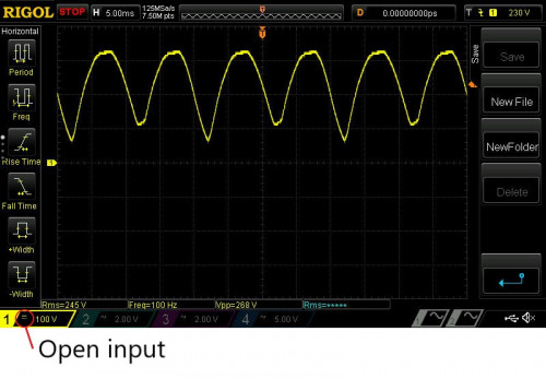
1. Open input (DC Coupling or Direct current) - indicated as "DC" or "=" on the oscilloscope screen. If the open input mode is selected, the input signal is not processed and is fed directly to the amplifier of the oscilloscope's vertical deflection system.
user posted image
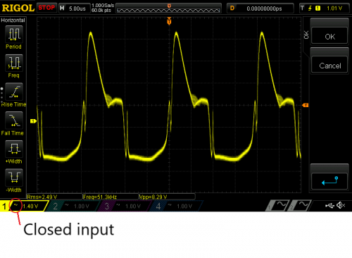
2. Closed input (AC Coupling or Alternating current) - indicated as "AC" or "~" on the oscilloscope screen. In the closed input mode, the constant component of the signal is filtered (simply put, the signal is fed to the amplifier of the system of vertical deviation of the oscilloscope in the same way as through the built-in capacitor), and the oscillogram is centered around a level of approximately 0 volts (ground) - without taking into account manual vertical displacement of the oscilloscope controls.
user posted image
3. Land. Indicated as “DC” or “Ʇ” on the oscilloscope screen. Disconnects the input signal from the input of the oscilloscope and closes the input of the oscilloscope to the instrument housing.

Why is this necessary:
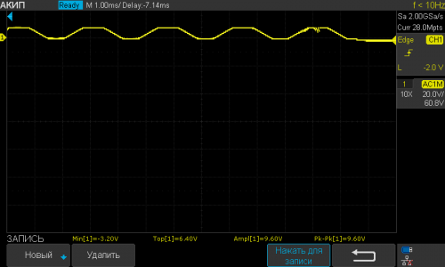
It is preferable to always use the oscilloscope in open-input mode - then the constant voltage displacements at the points in question are clearly visible. This is very important when debugging circuits with semiconductor devices: diodes, bipolar transistors and MOS transistors behave very differently depending on the presence and magnitude of the constant bias at their terminals! However, very often when debugging or repairing electronic devices, the signal at some points looks as follows (Fig. 1).
user posted image
Fig. 1

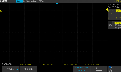
On which it is difficult to discern in detail the change in time of the signal. But this signal can be represented as the sum of two other signals: One of them is constant (Fig. 2)
user posted image
Fig. 2

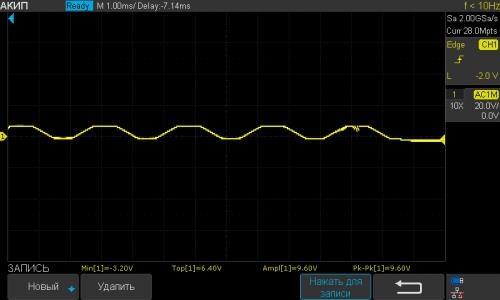
And the second (see. below. Fig. 3) varies in time relative to zero volts similarly and synchronously to the signal in Fig. 1.
user posted image
Fig. 3

Fig. 2 is called the constant component of the signal, and Fig. 3 - its variable component.

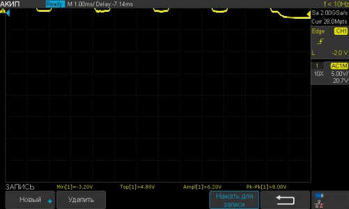
If we want to consider in detail how the signal in Fig. 1 varies in voltage, and we will begin to increase the gain of the channel of the vertical deviation of the oscilloscope - then we will increase its variable component, but at the same time the constant component of this signal will increase, and finally it will go beyond the scope of the oscilloscope, as in Fig. 4 - no matter how hard we try to compensate for this exit outside the window with the vertical beam shift handle!

user posted image
Fig. 4

Then, in order to consider in detail the change in time of the signal, it would be very convenient to simply exclude its constant component from the original signal, and in the future, simply amplify only its variable component. This is what happens after the corresponding channel is switched to the closed input mode, because the capacitor does not pass the constant component of the signal through itself. All that remains is to raise the gain of the channel of the vertical gain of the oscilloscope and obtain on its screen a detailed image of the change in the initial signal in time, as can be seen in Fig. 5.

user posted image
Fig. 5

This is one of the serious reasons for the availability of closed channels. But, when you make oscillograms in this mode, they do not have information about constant potentials (bias voltage) at these points.

Usually, the actions that need to be performed to transfer a channel from one operating mode to another are different for each manufacturer - but almost always the general principle is this:
1. By pressing the corresponding button 1, 2 ... select the necessary oscilloscope channel for operation (on / off, changing settings, etc.).
2. In the settings menu of this channel that appears on the screen, they find (usually understandable, by searching or according to the documentation for the oscilloscope) the corresponding item and press the button corresponding to this menu item, and then select the required input operating mode of this channel in the submenu that appears.

smile.gif The text is quite long, and I'm not sure that my translation into English will be immediately understandable. There are some terms that are generally accepted in my country, but a different combination of words may be accepted in your country. I apologize for that. I tried to check everything, but I’m ready for any clarifications.

    Have a good weekend! )))

Bit4ever P
post Jan 24 2020, 03:29 AM

New Member
*
Probation
7 posts

Joined: Jan 2020
Hello everyone, after several weeks of searching on the internet to find a solution to repair my S750, I came across this forum that changed my life.

Thanks to this I was able to repair my S750 which hadn't given any sign of life for a few years.

Many thanks to Lex and MichelD! rclxms.gif biggrin.gif thumbup.gif

I followed all the advice and replaced all the capacitors on the PSU board which allowed me to bring my S750 back to life. rclxm9.gif
I will now replace all the components of the AMP and Audio card.

However while trying to remove the glue from the audio card, I broke the C28 capacitor. Attached Image
I would like to know if this will affect the S750's operation? and I would also like to replace it, could someone please let me know its value (Farads)? icon_question.gif

Anyway one thing is for sure I'm not going to try to remove the damn glue from the audio card anymore, I don't want to do any more damage.

Thank you very much for creating and feeding this topic. thumbup.gif

MichalD
post Jan 24 2020, 04:31 AM

Getting Started
**
Junior Member
101 posts

Joined: Feb 2017
QUOTE(STREXNIN100 @ Jan 11 2020, 11:04 PM)
As a rule...
*
Hello after som time...many thanks for your detailed explanation, i need some time to absorb and understand all what you wroted smile.gif and make my own measurements to see differences between these modes.

Thank you very much. This weekend i will not be at home but next i will and check the measuring AD22 point.

MichalD
post Jan 24 2020, 06:14 AM

Getting Started
**
Junior Member
101 posts

Joined: Feb 2017
QUOTE(Bit4ever @ Jan 23 2020, 08:29 PM)
Hello everyone...
*
Hello,

good to hear that another S750 unit is brought back to life smile.gif

For the audio processing board, the broken C28 i think that will have some affect, if you are enough courageous you can try it what will it does, but not recommend, you can damage some other parts.

I can measure the value but only next weekend (not this comming, but next), i havent the board by my hand now.

I recommend you to scrape off all glue from the board, i know it is hard but not impossible, just a lot of "carefully ant work"
The glue can make conductive phantom traces after some time in next use.

Till now i scraped about 7 pcs of these smile.gif and another 3 pcs are waiting for it.

Good luck.


STREXNIN100 P
post Jan 27 2020, 12:54 AM

New Member
*
Probation
33 posts

Joined: Nov 2019


QUOTE(MichalD @ Jan 23 2020, 11:31 PM)
Hello...
Ok!
I'm still not sure that I wrote everything clearly. And most importantly, I’m not sure that I wrote what you were interested in, or I didn’t write completely ...
I will be happy to write everything I know, if it seems interesting to you!
Do not worry about the time!
I, too, am now a little busy with other things, and infrequently I can deal with my S750. ))

Bit4ever P
post Jan 27 2020, 12:55 AM

New Member
*
Probation
7 posts

Joined: Jan 2020
QUOTE(MichalD @ Jan 23 2020, 11:14 PM)
Hello,

good to hear that another S750 unit is brought back to life smile.gif

For the audio processing board, the broken C28 i think that will have some affect, if you are enough courageous you can try it what will it does, but not recommend, you can damage some other parts.

I can measure the value but only next weekend (not this comming, but next), i havent the board by my hand now.

I recommend you to scrape off all glue from the board, i know it is hard but not impossible, just a lot of "carefully ant work"
The glue can make conductive phantom traces after some time in next use.

Till now i scraped about 7 pcs of these smile.gif and another 3 pcs are waiting for it.

Good luck.
*
thank you for your answer and your help MichalD. i don't think i have enough courage to test the audio board with the missing C28 capacitor. blush.gif

Regarding the C28 value measurement,no problem I'll wait, anyway I'll receive the capacitors from the Amp and audio board this Monday, so I'll have something to do in the meantime. biggrin.gif

as for the glue, I think you're right thumbsup.gif and I don't like to see this brown thing on the board, so I'm going to totally remove it by taking even more precautions.


Bit4ever P
post Feb 1 2020, 10:36 PM

New Member
*
Probation
7 posts

Joined: Jan 2020
I finally removed all the glue from the audio card and replaced all the components biggrin.gif , this during with all the precautions taken, I broke a second C85 capacitor cry.gif Attached Image so I would also like to have its value if possible. Thanks in advance.
MichalD
post Feb 2 2020, 07:19 PM

Getting Started
**
Junior Member
101 posts

Joined: Feb 2017
QUOTE(Bit4ever @ Feb 1 2020, 03:36 PM)
I finally removed all the glue from the audio card...
*
Hello, i've desoldered the caps today and measured both for you.

C28...10,357 nF...so it will be 10nF nominal.
C85...10,732 nF...si it will be 10nF nominal too.
Bit4ever P
post Feb 2 2020, 10:54 PM

New Member
*
Probation
7 posts

Joined: Jan 2020
QUOTE(MichalD @ Feb 2 2020, 12:19 PM)
Hello, i've desoldered the caps today and measured both for you.

C28...10,357 nF...so it will be 10nF nominal.
C85...10,732 nF...si it will be 10nF nominal too.
*
hello thank you very much for your help MichalD notworthy.gif . i'm going to go buy and replace these two capacitors with 10nF as soon as possible. i would like to know if they are non-polarized capacitors? i'm going to replace them with conventional (not SMD) capacitors, that shouldn't be a problem, i think.
Bit4ever P
post Feb 2 2020, 11:02 PM

New Member
*
Probation
7 posts

Joined: Jan 2020
C28...10,357 nF...so it will be 10nF nominal.
C85...10,732 nF...si it will be 10nF nominal too

What do you think about the voltage ? I think 16V is good.
MichalD
post Feb 3 2020, 03:19 AM

Getting Started
**
Junior Member
101 posts

Joined: Feb 2017
QUOTE(Bit4ever @ Feb 2 2020, 04:02 PM)
What do you think about the voltage ?.
*
After checking this size of capacitors package 0.8x1.6mm it is rated for 16V so i think it will be enough.


33 Pages « < 26 27 28 29 30 > » Top
 

Change to:
| Lo-Fi Version
0.0149sec    0.39    6 queries    GZIP Disabled
Time is now: 28th March 2024 - 07:51 PM