


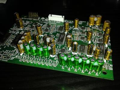
And here's a pic of the pcb with the new caps on. Nichicon Fine Gold and Nichicon Muse bipolars (sorry for the blurness).

This post has been edited by nautilus7: Jun 29 2018, 12:01 AM
PC Audio Creative GigaWorks S750 7.1 speaker repair, A short guide and info with pictures...
|
|
 Jun 28 2018, 11:01 PM Jun 28 2018, 11:01 PM
|

Newbie
20 posts Joined: Jun 2018 |
Fortunately I found the short... A big solder blob had dropped on the pcb and I hadn't noticed. I removed it using a pair of tweezers as it wasn't stuck well on the components.
And here's a pic of the pcb with the new caps on. Nichicon Fine Gold and Nichicon Muse bipolars (sorry for the blurness).
This post has been edited by nautilus7: Jun 29 2018, 12:01 AM |
|
|
|
|
|
Jun 29 2018, 01:21 AM
|
|
Junior Member
104 posts Joined: Feb 2017 |
QUOTE(nautilus7 @ Jun 28 2018, 12:16 AM) Hi, thanks for the fast response....connector please? Hello, i've measured that connector (input from power supply board) and all pins have its own potential, the is no short between each other pin. If you found some, there must be a fault.I will test more tomorrow and try to follow the traces on the pcb.  Here are two photos with unsoldered power supply connector from the board to view the PCB traces. 

This post has been edited by MichalD: Jun 29 2018, 01:48 AM |
|
|
Jun 29 2018, 01:38 AM
|
|
Junior Member
104 posts Joined: Feb 2017 |
QUOTE(nautilus7 @ Jun 28 2018, 04:01 PM) Fortunately I found the short...(sorry for the blurness). Great, nice job
 btw for the 2x6 pos. connector (flat ribbon to amplifier boards) does it have still shiny pins, or slightly oxidised or corroded? If it are still shiny, there is no need to replace. btw for the 2x6 pos. connector (flat ribbon to amplifier boards) does it have still shiny pins, or slightly oxidised or corroded? If it are still shiny, there is no need to replace. |
|
|
Jun 29 2018, 02:08 AM
|
|
Newbie
20 posts Joined: Jun 2018 |
Hi, thanks for the help.
The 2x6 pin connector in the pre-amp is still in good condition. I bought a replacement, but I chose not to put it in. I replaced the 2x6 connectors on the power amp boards though. They were oxidized. It was a pain in the ass to unsolder them and I slightly damaged the pads... |
|
|
Jun 29 2018, 02:31 AM
|
|
Junior Member
104 posts Joined: Feb 2017 |
QUOTE(nautilus7 @ Jun 28 2018, 07:08 PM) Hi, thanks for the help...damaged the pads... Hi, yes, i desoldered the 2x6 pin connector with ton of solder and heat it all at once and removed. I damaged the audio processing board some pads while removing the connectors, but i have all carefully repaired and lacquaered.No problem, glad to helped to you. |
|
|
Jul 3 2018, 06:51 AM
|
|
Newbie
20 posts Joined: Jun 2018 |
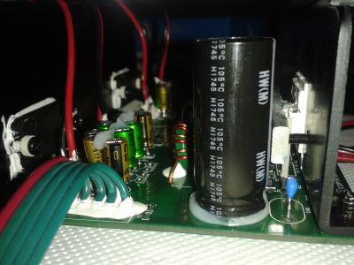
I have almost finished upgrading my Gigaworks set. The set was working fine, so it isn't really a repair, but an upgrade. Anyway, I guess it was a matter of time it would stop working because of the low quality capacitors used, so I chose to proceed. Following the great guide of MichalD, I replaced all electrolytic caps in the power supply board, as well as in the audio amp boards. Here are some photos of the finished amp boards.


|
|
|
|
|
|
Jul 6 2018, 04:20 AM
|
|
Junior Member
104 posts Joined: Feb 2017 |
QUOTE(nautilus7 @ Jul 2 2018, 11:51 PM) I have almost finished upgrading my Gigaworks set...finished amp boards. Nice, you have glued the amp board caps too, me not because they are very small and the replacements have much thicker and stronger legs than factory jun fu junk. I will see after some years if it will fail because of no glue This post has been edited by MichalD: Jul 6 2018, 04:21 AM |
|
|
Jul 6 2018, 06:21 AM
|
|
Newbie
20 posts Joined: Jun 2018 |
Hi, thanks!
I glued them not because I was afraid they will fail/break, but mainly because they are too close together and they can hit each other and vibrate. Don't forget they are inside a sub-woofer!  I used silicon (neutral cure, non corrosive) not glue, btw. |
|
|
Jul 7 2018, 04:24 AM
|
|
Junior Member
104 posts Joined: Feb 2017 |
QUOTE(nautilus7 @ Jul 5 2018, 11:21 PM) Hi, thanks!...I used silicon (neutral cure, non corrosive) not glue, btw. I soldered the amplifier caps with enough gap between to prevent touching each other. Time will show if it was enough...Yep, with glue i meant the neutral non corrosive silicone |
|
|
Oct 4 2018, 06:30 PM
|
|
Newbie
1 posts Joined: Oct 2018 |
Hello guys! Help please, you need a service manual for restoring the CREATIVE GigaWorks s750. Lost remote control lost amplifiers!
|
|
|
Oct 11 2018, 06:23 AM
|
|
Newbie
20 posts Joined: Jun 2018 |
I don't think there is a service manual... Only a schematic of the power board.
What is your problem? Is there anything that seem damaged on the boards? This post has been edited by nautilus7: Oct 11 2018, 06:25 AM |
|
|
Nov 20 2018, 03:24 AM
|
|
Newbie
1 posts Joined: Nov 2018 |
Hi everyone,
I bought myself a Creative Gigaworks S750 in ~2007, been very happy with it so far (except the overpowering sub even on it's lowest setting and maybe the lack of digital connectivity). Neighbours not so happy Anyway, a couple of years ago I experienced the blinking light problem, I found a handy friend who figured out one of the main power supply capacitors was failing, he replaced it and it worked perfect for years. A couple of weeks ago my wife started noticing a strange crackling sound. When she told me I looked in to it but noticed that by the time I looked into it the center, right and right side channel had no sound at all. Lucky me I have some handy colleagues who found out that one of the capacitors on one of the two amplifier boards was falling. We replaced both with new ones from Panasonic ( ECA2AHG102 ). Alle channels works great again! Unfortunately after some hours (?) of normal usage the crackling sound comes back on all channels. When I turn the speakers off (standby) and power them on the next day, the sound is gone for some time (I don't know exactly how long it takes, but I think It's more than an hour. It comes from the set itself as it also happens when I remove the input connections. I made a YouTube video of the sound (when I turn the mic to the speakers it gets more clearer to hear the sound). https://youtu.be/VzoiRcMbKFs Do any of you know what could cause this? This post has been edited by MavhRik: Nov 20 2018, 05:11 AM |
|
|
Dec 13 2018, 09:13 PM
|
|
Newbie
20 posts Joined: Jun 2018 |
Perhaps a visual inspection of all parts, especially in the power supply board, will reveal the problem. I can't tell from the video.
Some photos of the boards might help. |
|
|
|
|
|
Jan 12 2019, 07:33 PM
|
|
Newbie
2 posts Joined: Jan 2019 |
QUOTE(MichalD @ Mar 18 2018, 04:24 PM) Yep Hi! congratulations for your fantastic job! could I ask you to post the complete list of all the capacitors used? thank you so much!!! the TOP243Y's blue caps are X7R and "glued" with transparent PCB lacquer. And now i am not affraid of high temperature, check following:I have made a very comprehensive upgrades and repairs. Backplate: Whole subwoofer backplate with all electronics was dissasembled and the outside heatsing was removed too. Removed and cleaned all degraded glue and backplate was cleaned to aluminium gloss and all glue hard remants was grinded. All pure aluminium heat conductive surface connections was filled with heat conductive paste and the edges was glued to prevent vibrations. Between outside black aluminium heatsink and the backplate was added heat conductive paste too. New edge sealing and bass speaker sealing was applied. [attachmentid=9697954][attachmentid=9697955][attachmentid=9668880] [attachmentid=9668883][attachmentid=9744125] AMP boards, APB board and I/O board: All electrolytic caps on amplifier boards and audio processing board was replaced by ELNA RFS Silmic II and bipolars was replaced by Nichicon MUSE. [attachmentid=9668888][attachmentid=9668887][attachmentid=9668889][attachmentid=9697957] [attachmentid=9697958][attachmentid=9697960][attachmentid=9668892] All factory glued connectors and PCB pins was replaced by new ones and all wire contact was crimped with new contact crimps. [attachmentid=9668891][attachmentid=9697961][attachmentid=9697981][attachmentid=9697982] Audio processing board was separated from I/O board and soldered new contact pins and headers to make it detacheable. Input cable was removed and soldered JST-XH 8 pin header and custom cable made for connection to PSU board. New custom made signal cable from audio processing board to amp boards used. Almost all cables was tied together with cable ties. Removed all degraded glue from I/O board and I/O connectors was resoldered with fresh solder. Replaced all JST-VH conn headers. [attachmentid=9697963][attachmentid=9697964][attachmentid=9697966][attachmentid=9697967] [attachmentid=9697994][attachmentid=9697976][attachmentid=9697968][attachmentid=9668951] PSU board: Replaced mains power switch and grid input connector with grounding pin connected to backplate with yellow/green wire. [attachmentid=9697969][attachmentid=9697970][attachmentid=9697971][attachmentid=9697972][attachmentid=9697973][attachmentid=9697975][attachmentid=9668896] Replaced all electrolytic caps for high quality ones (Nichicon, Rubycon) and the most of ceramic caps. [attachmentid=9668900][attachmentid=9744111][attachmentid=9744113][attachmentid=9744114][attachmentid=9744115] [attachmentid=9744117][attachmentid=9744118][attachmentid=9744120][attachmentid=9744121][attachmentid=9744122] [attachmentid=9744123][attachmentid=9744124] Replaced all TO220's aluminium oxide heat conductive pads (lot of them brokes when disassembled) with heat conductive paste. Custom made linear reg / diode heatsink, shape silmiliar to IRF740 heatsink. Custom made carrying L shape heatsink. Added ribbed heatsink for better heat dissipation. (ebay sourced) [attachmentid=9668902] All heat sink connection surface filled with heat conductive pad sheet. All screwed together and screws was glued or transparent protective PCB lacquer lacquered to prevent unscrewing. The most important thing was connect the carrying L shape heatsink to backplate with heat conductive paste for best heat dissipation and tightened using 6 screws with self locking nut and the edges was glued. [attachmentid=9668904][attachmentid=9697977] Part of PCB copper pad under heatsink connection near D13 was scraped off to make it unconductive to heatsink. Heatsink side of L11 near C20 was unsoldered and heatshrinked and glued to PCB. [attachmentid=9668907] [attachmentid=9668911] This makes the heatsink conductive isolated from the power supply board and the mains grounding wire can be safely connected to backplate and now can fulfill its function. [attachmentid=9697978][attachmentid=9668898] After this upgrade the heat dissipation is much more better than original which can guarantee much much longer lifespan. In the standby mode the outer heatsink is hand touch cold. In power on and common use the backplate and heat sink after some time are hand touch warm but not hot (about 35-40°C). For the even better heat dissipation the outside heatsink can be equipped with FAN which can lower the temperature to lukewarm if used low rpm and low noise FAN. [attachmentid=9668912] Upgraded active cooling with 140mm low noise FAN less than 20dB at full rated speed. [attachmentid=9697979][attachmentid=9697980] Wooden case: Wooden case all internal edges was reiforced with new glue and after then whole case was damped with wadding filling. Bassreflex pipe was removed and newly glued. [attachmentid=9697983][attachmentid=9697984][attachmentid=9697985] [attachmentid=9697986][attachmentid=9668913][attachmentid=9668916] All inside [attachmentid=9697987][attachmentid=9697988][attachmentid=9697989][attachmentid=9697990][attachmentid=9697991] After this case upgrade the bass are deeper and louder about 2-3 dB compared with the wooden case with no filling. Compared both with the same master volume and SUB volume settings.  |
|
|
Jan 26 2019, 09:38 AM
|
|
Newbie
3 posts Joined: Jun 2015 |
Guys, I'm on a short budget to repair my S750. Buying those caps from Mouser/Digi too expensive for me for its $70+ shipping fare. Do you know a good seller which selling those genuine branded caps on AliExpress? I can't distinguish it at all. Any advice? Thank You!
|
|
|
Feb 12 2019, 06:18 AM
|
|
Junior Member
104 posts Joined: Feb 2017 |
QUOTE(Zazax @ Jan 12 2019, 12:33 PM) Hi! congratulations for your fantastic job! could I ask you to post the complete list of all the capacitors used? thank you so much!!! Hello, thank you. Here is the capacitor list i've used:PSU board: CK45-R3AD221K-NRA CAP CER 220PF 1KV RADIAL C2 30 28 29 RDER73A471K2K1H03B CAP CER 470PF 1KV X7R RADIAL C39 35 36 37 38 AR205F104K4R CAP CER 0.1UF 50V X8R RADIAL C63 LGR2D471MELZ40 CAP ALUM 470UF 20% 200V SNAP C59 60 69 70 100ZLJ330M12.5X35 CAP ALUM 330UF 20% 100V RADIAL C71 72 35ZLJ220M8X16 CAP ALUM 220UF 20% 35V RADIAL C64 73 74 75 76 50ZLJ100MT78X11.5 CAP ALUM 100UF 20% 50V RADIAL C65 78 66 67 77 450BXW68MEFR14.5X40 CAP ALUM 68UF 20% 450V T/H C61 35ZLJ47M5X11 CAP ALUM 47UF 20% 35V RADIAL C68 62 DE1B3KX471KA4BP01F CAP CER 470PF 300VAC RADIAL C7 CC45SL3FD470JYNNA CAP CER 47PF 3KV SL RADIAL C3 C317C101K2R5TA CAP CER 100PF 200V X7R RADIAL C9 46 45 44 43 42 41 40 RDER73A332K2K1H03B CAP CER 3300PF 1KV X7R RADIAL C6 RDER72J103K2M1H03A CAP CER 10000PF 630V X7R RADIAL C20 19 17 18 RDER72A104K1K1H03B CAP CER 0.1UF 100V X7R RADIAL C11 53 12 13 52 10 48 49 50 79 RDER73A472K2K1H03B CAP CER 4700PF 1KV X7R RADIAL C8 Amplifier boards: UHW2A102MHD CAP ALUM 1000UF 20% 100V RADIAL C39 FK22X7R2A105K CAP CER 1UF 100V X7R RADIAL C40 RFS-50V2R2ME3#5 CAP ALUM 2.2UF 20% 50V RADIAL C86 89 85 88 84 87 91 81 RFS-50V220MH3#5 CAP ALUM 22UF 20% 50V RADIAL C79 83 78 82 77 90 UES1H4R7MEM CAP ALUM 4.7UF 20% 50V RADIAL C28 69 22 37 27 68 21 36 26 67 20 35 80 Audio processing board: RFS-16V470MG3#5 CAP ALUM 47UF 20% 16V RADIAL APB C208 RFS-16V100ME3#5 CAP ALUM 10UF 20% 16V RADIAL APB all 10uF RFS-50V220MH3#5 CAP ALUM 22UF 20% 50V RADIAL APB C211 RFS-16V101MH3#5 CAP ALUM 100UF 20% 16V RADIAL APB C220 218 202 201 221 219 UES1H4R7MEM CAP ALUM 4.7UF 20% 50V RADIAL APB C54 52 58 56 39 40 16 18 17 15 Relay clicking issue fix: FG20X7R1H106KRT06 CAP CER 10UF 50V X7R RADIAL added another C63 FK26X7R2A104K CAP CER 0.1UF 100V X7R RADIAL added between TOP243Y's C and S PIN FK26X7R2A105K CAP CER 1UF 100V X7R RADIAL added between TOP243Y's C and S PIN This post has been edited by MichalD: May 15 2019, 03:24 AM |
|
|
Feb 12 2019, 06:46 PM
|
|
Newbie
2 posts Joined: Jan 2019 |
QUOTE(MichalD @ Feb 11 2019, 11:18 PM) Hello, thank you. Here is the capacitor list i've used: Thank you so much! I think it will be appreciated by many of us! PSU board: CK45-R3AD221K-NRA CAP CER 220PF 1KV RADIAL C2 30 28 29 RDER73A471K2K1H03B CAP CER 470PF 1KV X7R RADIAL C39 35 36 37 38 AR205F104K4R CAP CER 0.1UF 50V X8R RADIAL C63 LGR2D471MELZ40 CAP ALUM 470UF 20% 200V SNAP C59 60 69 70 100ZLJ330M12.5X35 CAP ALUM 330UF 20% 100V RADIAL C71 72 35ZLJ220M8X16 CAP ALUM 220UF 20% 35V RADIAL C64 73 74 75 76 50ZLJ100MT78X11.5 CAP ALUM 100UF 20% 50V RADIAL C65 78 66 67 77 450BXW68MEFR14.5X40 CAP ALUM 68UF 20% 450V T/H C61 35ZLJ47M5X11 CAP ALUM 47UF 20% 35V RADIAL C68 62 DE1B3KX471KA4BP01F CAP CER 470PF 300VAC RADIAL C7 CC45SL3FD470JYNNA CAP CER 47PF 3KV SL RADIAL C3 C317C101K2R5TA CAP CER 100PF 200V X7R RADIAL C9 46 45 44 43 42 41 40 RDER73A332K2K1H03B CAP CER 3300PF 1KV X7R RADIAL C6 RDER72J103K2M1H03A CAP CER 10000PF 630V X7R RADIAL C20 19 17 18 RDER72A104K1K1H03B CAP CER 0.1UF 100V X7R RADIAL C11 53 12 13 52 10 48 49 50 79 RDER73A472K2K1H03B CAP CER 4700PF 1KV X7R RADIAL C8 Amplifier boards: UHW2A102MHD CAP ALUM 1000UF 20% 100V RADIAL C39 FK22X7R2A105K CAP CER 1UF 100V X7R RADIAL C40 RFS-50V2R2ME3#5 CAP ALUM 2.2UF 20% 50V RADIAL C86 89 85 88 84 87 91 81 RFS-50V220MH3#5 CAP ALUM 22UF 20% 50V RADIAL C211 79 83 78 82 77 90 UES1H4R7MEM CAP ALUM 4.7UF 20% 50V RADIAL C28 69 22 37 27 68 21 36 26 67 20 35 80 Audio processing board: RFS-16V470MG3#5 CAP ALUM 47UF 20% 16V RADIAL APB C208 RFS-16V100ME3#5 CAP ALUM 10UF 20% 16V RADIAL APB all 10uF RFS-16V101MH3#5 CAP ALUM 100UF 20% 16V RADIAL APB C220 218 202 201 221 219 UES1H4R7MEM CAP ALUM 4.7UF 20% 50V RADIAL APB C54 52 58 56 39 40 16 18 17 15 Relay clicking issue fix: FG20X7R1H106KRT06 CAP CER 10UF 50V X7R RADIAL added another C63 FK26X7R2A104K CAP CER 0.1UF 100V X7R RADIAL added between TOP243Y's C and S PIN FK26X7R2A105K CAP CER 1UF 100V X7R RADIAL added between TOP243Y's C and S PIN |
|
|
Feb 21 2019, 05:38 AM
|
|
Newbie
20 posts Joined: Jun 2018 |
This is my restoration, which I did in 2018 (took about 5 months). I followed MIchalD's instructions and suggestions, who I would like to thank publicly as well.
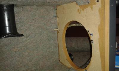
My gigaworks set did not have any problem (it was working fine, except from the relay clicking issue), since it hasn't played for so many hours though. I thought it would eventually show the same problems as most users here are facing, so I decided to go on with the restoration. Some things worth mentionng for my restoration: I replaced all electrolytic and cheap ceramic capacitors in the psu board as well as in the audio processing and the power-amp boards. I also replaced all connectors, some cables, diodes, the power switch and maybe even more parts I forget now. The total cost was about €200 and around €100 more for some tools I needed. All electronic parts were bought from Mouser. It may sound too much, but the restoration is certainly possible with less money (for example changing only the electrolytics on the psu board). I changed the mounting orientation of the psu board, both in the L-shaped bracket (in a way that the heatsinks make contact with it) and also in the backplate, so I can use it for heat dissipation. In addition, I put thermal paste in between all metal parts (the L-shaped bracket, the power amp heatsinks and the external heat sink). Where the psu board was damaged (the solder mask was destroyed by the corrosive glue used for the capacitors) I reapplied UV curable solder mask (bought from ebay). For the mains input capacitors, some of the pads were destroyed when removing the caps, so I used external wires in the back of the board to connect them properly. Finally, I covered the subwoofer box with 8mm thick felt. Among with the new caps in the the audio boards, I think it sounds a little bit better now. 


|
|
|
Feb 21 2019, 06:04 AM
|
|
Junior Member
104 posts Joined: Feb 2017 |
QUOTE(nautilus7 @ Feb 20 2019, 10:38 PM) This is my restoration, which I did in 2018... Finaly you are done with your set, great job  . I like your red/black wiring, you have shorted the wires just for necessary length. Very nice! . I like your red/black wiring, you have shorted the wires just for necessary length. Very nice!What about the relay clicking issue in your case, it's gone too? |
|
|
Feb 22 2019, 02:05 AM
|
|
Newbie
1 posts Joined: Feb 2019 |
Hello everyone. I have a S750 with no power. Replaced the fuse but the new one blew up. Can't you please point me in the right direction. I can't see any blown capacitors, but in D10 there's some burn marks.


|
| Change to: |  0.0381sec 0.0381sec
 0.30 0.30
 6 queries 6 queries
 GZIP Disabled GZIP Disabled
Time is now: 13th December 2025 - 01:30 AM |
 Quote
Quote