Welcome Guest ( Log In | Register )

35 Pages « < 7 8 9 10 11 > » Bottom

Outline · [ Standard ] · Linear+

Hobbies Electronics Enthusiasts Club, All elect/robotics lovers! pls come!

views
     
ngwinnie
post Sep 6 2006, 11:55 PM

Getting Started
**
Junior Member
107 posts

Joined: Sep 2006
From: KL


QUOTE(Ethan @ Apr 27 2006, 09:50 PM)
Robotics hobbyist might be interested here......

ROBOCON Malaysia 2006 will be held at PWTC next weeked (6-7 May).
Competing teams include MMU, UTM (defending champion), Uniten, UKM and others.

Check it out.
*
I heard that they're gonna have the international one in PWTC too. Anyone knows what time it starts? Or whether its free admission?
MrNobody
post Sep 7 2006, 01:45 AM

New Member
*
Junior Member
9 posts

Joined: Jul 2006
Hi,
I am doing project for college.
Actually, it is a clothes dryer project using light sensor.
whenever there is light, the clothes will come out to be exposed to the sun and whenever it is dark, the clothes will go into the shed.
It is a motorized dryer...
For the project, I intend to classify the light intensity at 6pm as 'dark'.. In another words, i want the clothes to go in automatically at around 6.. In order to do that, i need to know what is the light intensity at 6pm (preferably in lux). Does anybody know what is the light intensity at 6pm or does anybody know where i can get the info..?
Thanks..
allan28
post Sep 7 2006, 07:52 PM

New Member
*
Junior Member
16 posts

Joined: Mar 2005
QUOTE(ngwinnie @ Sep 6 2006, 11:55 PM)
I heard that they're gonna have the international one in PWTC too. Anyone knows what time it starts? Or whether its free admission?
*
yes...the ABU level ROBOCON 2006 will be held in PWTC this sunday (10 Sept)...
the preliminary rounds will start from morning 8 or 9sth...then wil go on til evening where there will be live telecast tru TV1 (semifinal & final match only)....
i'm not so sure bout the admission...
below is the official site for this year robocon...

http://www.robofest.org.my/robocon2006/international.html
jedi_master
post Sep 8 2006, 02:40 PM

Getting Started
**
Junior Member
165 posts

Joined: Jan 2005
From: Soul Society


Lets go to Robocon everyone! biggrin.gif

For those of you who entered, but did not make it to the internationals, it's ok!

Just put on that yellow robocon t-shirt which is gathering dust in your cupboard and come along! icon_idea.gif

rclxm9.gif rclxm9.gif rclxm9.gif rclxm9.gif rclxm9.gif rclxm9.gif

lol... trying to increase hype for robocon here


knight
post Sep 8 2006, 04:41 PM

The Truth is Out There..
******
Senior Member
1,842 posts

Joined: Jan 2003


QUOTE(MrNobody @ Sep 7 2006, 01:45 AM)
Hi,
I am doing project for college.
Actually, it is a clothes dryer project using light sensor.
whenever there is light, the clothes will come out to be exposed to the sun and whenever it is dark, the clothes will go into the shed.
It is a motorized dryer...
For the project, I intend to classify the light intensity at 6pm as 'dark'.. In another words, i want the clothes to go in automatically at around 6.. In order to do that, i need to know what is the light intensity at 6pm (preferably in lux). Does anybody know what is the light intensity at 6pm or does anybody know where i can get the info..?
Thanks..
*
U doin this for ur final year project or for ur college???

Well, refering to what has Chowsc has posted b4 did u go and check thoes usefull website?? My oppinion was, U should do more homework b4 posting this...the link chowsc posted have it..very similar i think..u juz need to modify
Regarding to the light intensite at 6pm, no one knows coz the light intensity for whole year and not the same..i think u should juz let it detect the sun and the sensor will put it outside...well, it's might be an easy project coz it does not require a PIC but certain ICs..Correct me if i'm wrong..Good Luck dude...
Scud_eSpade
post Sep 13 2006, 10:10 AM

Casual
***
Junior Member
345 posts

Joined: Dec 2004
From: B. B. Bangi


anyone can recommend me other electronic shop around kl beside at the jalan pasar?
fx_53_xt
post Sep 15 2006, 02:38 AM

Look at all my stars!!
*******
Senior Member
2,048 posts

Joined: Oct 2004


hi all, got an assignment going on here tat need some idea from you guys...
i need to construct a DC power supply which takes in 240v AC and have 3.3v,5v,12v,15v and 24v output which have max 250mA load...

here is my idea :

1) AC line -> fuse -> transformer (step down to 24v) -> rectifier -> capacitor (filtering) -> resistor to further step down to each lower value

2) AC line -> fuse -> 5 transformer (step down to each of the 5 values) -> capacitor -> output

which one is practical?
kerry
post Sep 15 2006, 11:39 AM

Casual
***
Junior Member
327 posts

Joined: Jan 2003
From: Tmn Melawati, K.L.


depending on how you want to use it for!

Are you going to use all at the same time?

Anyway, don't use resistor to reduce voltage. better use regulator or at least zener diode.


fx_53_xt
post Sep 15 2006, 12:33 PM

Look at all my stars!!
*******
Senior Member
2,048 posts

Joined: Oct 2004


5 transformer seems a lil too ridiculous...
since lecturer say there is only one physical output needed, i choosen to use reostat.

anyway, when it says 24v DC output, does it means peak voltage, RMS voltage or average voltage should be 24v?
harrychoo
post Sep 15 2006, 01:29 PM

Look at all my stars!!
*******
Senior Member
3,589 posts

Joined: Mar 2005
From: Bolehland


24V-0V-24V is rms value. multiply with sqrt2.

use 1 transformer then use few regulators, 78xx series.

or if u got money, get MVR (Multi Voltage Regulator) used in those car audio system
kerry
post Sep 15 2006, 09:40 PM

Casual
***
Junior Member
327 posts

Joined: Jan 2003
From: Tmn Melawati, K.L.


If only using one concurrent output IMO you're better off with;
15-0-15 txformer
LM317 regulator + resistor network
dextermia
post Sep 21 2006, 08:55 PM

Getting Started
**
Junior Member
107 posts

Joined: Oct 2005

anyone know where i can get this kind of electronic snap circuits around KL ?

user posted image
zackertashia
post Sep 21 2006, 11:12 PM

Getting Started
**
Junior Member
265 posts

Joined: Jan 2003

hi guys..im a total noob wen it comes to electronics but im slowly learning hoping to one day able to design my own circuitries..i must say those are very interesting web links u guys posted on d first page..

hope sumbody cud help me ere..im intending to do a signal modification to my bike ere but as im still in d process of learning i wud need sifoos help ere:)on my bike ther is no hazard light as such on bigger bikes..wat im tryin to do is to fix a circuit for hazard light on my bike using the existing signal lights..anybody care to help?

lemme kno if anybody need me to further elaborate anything..thanx thumbup.gif
knight
post Nov 29 2006, 04:16 PM

The Truth is Out There..
******
Senior Member
1,842 posts

Joined: Jan 2003


wow...where is ChowSC??? this thread like been deserted for month...

here i got a question to ask, any1 know how to amplify 0.1mA to 15mA?? any idea to amplify this?? I tried using UA741 but wonder is there anywrong in the circuitry..
TSchowsc
post Nov 30 2006, 12:28 AM

https://www.facebook.com/yuanyancafe
****
Senior Member
657 posts

Joined: Jan 2003
From: Serdang, Bentong(Pahang)


^^ me here all the time, jsut that some questions i couldnt answer and not many ppl coming in ...sigh ....hope that this thread wont die so soon ^^
xenon
post Nov 30 2006, 08:00 AM

On my way
****
Senior Member
502 posts

Joined: Jan 2005
From: Selangor

QUOTE(knight @ Nov 29 2006, 04:16 PM)
any1 know how to amplify 0.1mA to 15mA?
*
Is it that you want to design a linear current amplifier? That is input of 0.01mA will get output of 1.5mA as well. You should tell more about what kind of signal you want to amplify. What range or amplitude is the input signal, what input and output impedance you expect, and range of frequency of the signal.
knight
post Nov 30 2006, 08:27 PM

The Truth is Out There..
******
Senior Member
1,842 posts

Joined: Jan 2003


nice...make the thread alive..haha...

actually, the 0.1mA comes from a photosensor...and this signal i need to feedback to my PIC to process some information..there for 0.1mA can't switch on a normal transistor..it's too small...so i thought of using an current amplifier using op amp...but wonder y it does not work...
xenon
post Nov 30 2006, 08:52 PM

On my way
****
Senior Member
502 posts

Joined: Jan 2005
From: Selangor

So, you use ADC of PIC, that should be voltage, not current. Then, can give more details about your photosensor? If it is photodiode or photoresistor (LDR), you might be able to make it simple; it shouldn't need amplification, just use correct resistor value to bias or form voltage divider.

This post has been edited by xenon: Nov 30 2006, 08:54 PM
knight
post Nov 30 2006, 09:01 PM

The Truth is Out There..
******
Senior Member
1,842 posts

Joined: Jan 2003


I dun need ADC coz I dun need to know the distance...^^...my sensor was obp704...come with both Diode and phototransistor...and i just need to feedback voltage of 5v to my PIC...
xenon
post Nov 30 2006, 09:35 PM

On my way
****
Senior Member
502 posts

Joined: Jan 2005
From: Selangor

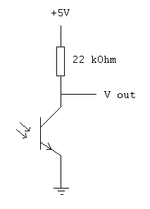
Why don't you do something like this?
Attached Image

By circuit analysis, when the phototransistor is conducting 200uA, Vout is 0.6V. When phototransistor is not conducting, Vout is 5V. You should use ADC, unless you have a PIC with analog comparator. But then using analog comparator still not as straightforward as ADC. So I will definitely use ADC: very simple electronic circuit. Threshold and Schmitt trigger behaviour easily programmed. And simple to program with ADC.

35 Pages « < 7 8 9 10 11 > » Top
 

Change to:
| Lo-Fi Version
0.1068sec    0.88    6 queries    GZIP Disabled
Time is now: 27th November 2025 - 10:08 AM