Welcome Guest ( Log In | Register )

Outline · [ Standard ] · Linear+

Hobbies Electronics Enthusiasts Club, All elect/robotics lovers! pls come!

views
     
xenon
post Jan 1 2006, 10:14 PM

On my way
****
Senior Member
502 posts

Joined: Jan 2005
From: Selangor

Hmm.. wonder how many of you have personal computers with (printer) parallel port and (RS-232) serial port. The future will be without those while I am still relying on parallel port a lot. Programming microcontrollers and flashing Nokia 3310 firmware.

I'm now looking at Microchip's microcontroller with USB support. Thinking of playing with USB. Can anyone tell where to get USB connector? Perhaps I start by making a smart card reader that plugs into USB. Yeah, I'm also looking for smart card connector.
xenon
post Jan 3 2006, 09:18 PM

On my way
****
Senior Member
502 posts

Joined: Jan 2005
From: Selangor

Easy to get smart card reader? Can talk about it in more details? I want to know how much do I need to pay to get one. Not USB then what? Serial port, not available to some computers.
xenon
post Jan 5 2006, 08:02 PM

On my way
****
Senior Member
502 posts

Joined: Jan 2005
From: Selangor

huhuhu samples...

Microchip - deliver using FedEx. good, but don't misuse it.
Analog Devices - not for Malaysia. But if you have an address in USA...
Maxim/Dallas Semiconductor - using normal mail. But I didn't receive my order a month ago.
National Semiconductor - no response. and I didn't bother to email them.
Fairchild Semiconductor - no response
Texas Instruments - using a courier service, comes in a box. Even give you expensive digital signal processors.
Cirrus Logic - didn't try
Linear Technologies - didn't try
Freescale (previously Motorola) -didn't try
ON Semiconductor - no response
Intel - I actually got samples of flash memory chips. But that is only available at that time.


Vishay - call my handphone and ask for purpose. No samples for non-commercial projects. (no money return no talk)

RTI Electronics - I got a few thermistors
Coilcraft - E-mailed to ask about student policy. Seems complicated - leceh
Cooper Electronic Technologies - only ordered printed catalog. and I received it.
xenon
post Jan 16 2006, 07:16 AM

On my way
****
Senior Member
502 posts

Joined: Jan 2005
From: Selangor

Can bump one meh?

How much is the cheapest digital multimeter sold at Jalan Pasar shops? I bought the DT-830D in Kuantan for RM15 last time. Now see Carrefour sells it for RM60. Now thinking of buying a cheap digital multimeter because my probe wires are broken. And sometimes I want to measure voltage and current at the same time.

My DT-830D is really accurate for the 20 volt range. I tested it in the lab of my university. All digits correct.
xenon
post Feb 6 2006, 09:53 PM

On my way
****
Senior Member
502 posts

Joined: Jan 2005
From: Selangor

I got my smart card reader working. Now playing with MyKad. Reverse-engineering, hehe.

Success: reading out the JPEG photo. It's slightly less than 4000 bytes, 150x200 pixels.

Cracking head on the thumbprint format. Found standards specifying 6 bytes per minutia. But what I found on my card looks like 4 bytes per minutia. The data that I'm looking at matches the description "500 bytes per print". The header at the beginning contains the string "R1L1".
xenon
post Feb 17 2006, 07:49 AM

On my way
****
Senior Member
502 posts

Joined: Jan 2005
From: Selangor

For PIC programmer, last time I used WinPic http://www.qsl.net/dl4yhf/winpicpr.html
I suggest you to make a second attempt to build yourself.
The basic blocks you need are

1) 5V power supply (built from an AC-DC adapter, connector for DC power jack, 7805 regulator + electrolytic capacitors)

2) Parallel port connector + 4 to 6 wires of 1 meter each

3) Protoboard and the PIC chip

4) Supporting circuit. I can design a simple one for you, after you tell which PIC chip you want to program. Generally there are two solutions. One is using a logic chip that can tri-state eg. 74HC244. The other is using a few NPN transistors and a few resistors. Then recently I tried a third solution, throw away all the supporting circuit stuff and connect directly to the parallel port, utilising the bidirectional data capability. We cannot use WinPic in the third solution but I wrote my own program. In the third solution, the only components needed are three 220pF capacitors.

Since most of the PICs have two programming modes, first one requires 13V but the second mode doesn't require, we don't need to provide 13V. The supporting circuit is really simple. All you need to do now is get the items 1) 2) 3) above ready, then state the part number of your PIC chip. And whether you choose solution one: logic chip; or two: npn transistors, eg C945, C9013, BC547, 2N3904
xenon
post Feb 18 2006, 06:20 AM

On my way
****
Senior Member
502 posts

Joined: Jan 2005
From: Selangor

2N3906 is PNP.

5 volt. Stressing the chip with 6 volt is not good. The datasheet recommends the maximum operating suppy voltage to be 5.5V. Lowest is 4.0V. Three batteries maybe? If you use NiMH batteries, the voltage per cell is about 1.25-1.45. For alkaline, 1.10V for low battery condition to 1.60V fresh from package. As you can see one cell is not 1.5V fixed, using a voltage regulator is almost a must.

When using LM7805 regulator, you need at least 7V input to the regulator to get 5V output.

Breadboard (also called protoboard) - project board.

I'm a bit busy for this few weeks. So I don't have time to test an NPN transistor solution. Probably have to wait for a week or so.
xenon
post Jun 16 2006, 03:30 PM

On my way
****
Senior Member
502 posts

Joined: Jan 2005
From: Selangor

CD-ROM drive spindle motor. For example
http://www.angelfire.com/blues/heli_project/brushless.htm

But the motors usually require both 5V and 12V to operate. 5V for controller and 12V for motor drive. It is perfectly ok to supply 5V instead of 12V for motor drive, but you will not get the power you want.
xenon
post Nov 30 2006, 08:00 AM

On my way
****
Senior Member
502 posts

Joined: Jan 2005
From: Selangor

QUOTE(knight @ Nov 29 2006, 04:16 PM)
any1 know how to amplify 0.1mA to 15mA?
*
Is it that you want to design a linear current amplifier? That is input of 0.01mA will get output of 1.5mA as well. You should tell more about what kind of signal you want to amplify. What range or amplitude is the input signal, what input and output impedance you expect, and range of frequency of the signal.
xenon
post Nov 30 2006, 08:52 PM

On my way
****
Senior Member
502 posts

Joined: Jan 2005
From: Selangor

So, you use ADC of PIC, that should be voltage, not current. Then, can give more details about your photosensor? If it is photodiode or photoresistor (LDR), you might be able to make it simple; it shouldn't need amplification, just use correct resistor value to bias or form voltage divider.

This post has been edited by xenon: Nov 30 2006, 08:54 PM
xenon
post Nov 30 2006, 09:35 PM

On my way
****
Senior Member
502 posts

Joined: Jan 2005
From: Selangor

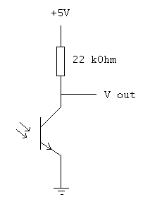
Why don't you do something like this?
Attached Image

By circuit analysis, when the phototransistor is conducting 200uA, Vout is 0.6V. When phototransistor is not conducting, Vout is 5V. You should use ADC, unless you have a PIC with analog comparator. But then using analog comparator still not as straightforward as ADC. So I will definitely use ADC: very simple electronic circuit. Threshold and Schmitt trigger behaviour easily programmed. And simple to program with ADC.
xenon
post Dec 6 2006, 05:28 PM

On my way
****
Senior Member
502 posts

Joined: Jan 2005
From: Selangor

What does this "amplify a 5v to 12v" has to do with the original light sensor? You are using a 5V PIC aren't you?

There is a flaw with my 22kOhm design because that makes input impedance seen by ADC become 22kOhm, while the maximum recommended is 10kOhm. However using 22kOhm won't cause it fail completely, it's just the acquisition time is lengthened. Nevertheless, changing 22kOhm to 10kOhm resistor also works.

If you're using opamp to improve the input impedance seen by ADC, the opamp should be powered by 5V and 0V, voltage follower circuit. But opamp is not necessary. Adding gain here is like nonsense to me.

Can you measure the output voltage of what I've shown? It should be more than 4V for one condition and less than 3V for another condition. Don't forget to power on the LED (IRED actually). And one more thing, did you burn the LED? (because many of my friend did this kind of mistake of not having correct resistor in series with LED; you must not connect LED to a voltage source without a resistor)
xenon
post Dec 6 2006, 06:19 PM

On my way
****
Senior Member
502 posts

Joined: Jan 2005
From: Selangor

^ Wrong circuit. Is up there, between resistor and collector, connect to PIC16F877. Measure the voltage, red probe on collector, black probe on ground.


Change to:
| Lo-Fi Version
0.0292sec    0.72    7 queries    GZIP Disabled
Time is now: 25th November 2025 - 11:07 PM