Need cut both since it needs live and neutral. Live to neutral at input is for the ESP chip in the Basic. Live to neutral at output is for the load. Never seen you post something regarding any Smart device you have. Inb4 smart device is inside your brain.
Yes. My smart device is in my imagination. I have yet to install anything "smart", something can be monitored/controlled remotely. I just need to walk to switch and visually check the switches before going to sleep
Maybe I misunderstood here. The Sonoff he was talking about is the Sonoff Basic WiFi (popular one here) right?
I imagine you are putting the Sonoff at the lighting point. So, no wire to cut. Just need L and N to power the unit, right? The Label at output L and N is confusing as I see it. The output side is just like SPST switch if you look at the PCBA diagram. Am I right?
What do mean by 'tap join'? Disconnect and connect back to the Basic? Still need to connect the output from Basic to the load.
I mean not need to actually cut the loop since it is not single piece wire to really cut it. Just break the join to replace the load with sonoff and connect the load to sonoff.
anyone have any idea how to pull neutral using existing conceal konduit? or r u just do so obvious surface wiring.
Depends on how far from N location.
1) Cut wall. Lay wire and conceal. This is more practical during renovation 2) Make a wall panel (faux wall) and put wire behind it 3) Just put on surface
What is your plan? Can't use a switch that require no N?
Have to use improvised cable puller by using another 2.5mm wire. Direct poke new wire into the conduit doesn't go too far.
Too many wire in conduit is not good too. Look nice on top but the ability to carry current drop as you added more and more wire in conduit. Probably not much a problem for low load
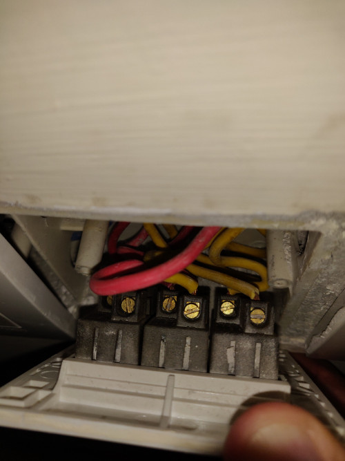
Anyone knows which is is neutral wire. Planning to install sonoff tx 2 gang switch.
Switch do not have Neural wire. I think your house is 3 phase wiring. That's why you have Red, Blue and Yellow of each phase. Is there any other color there?
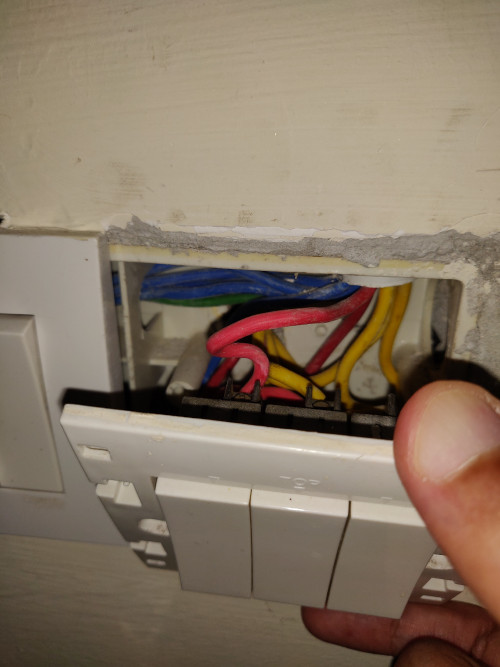
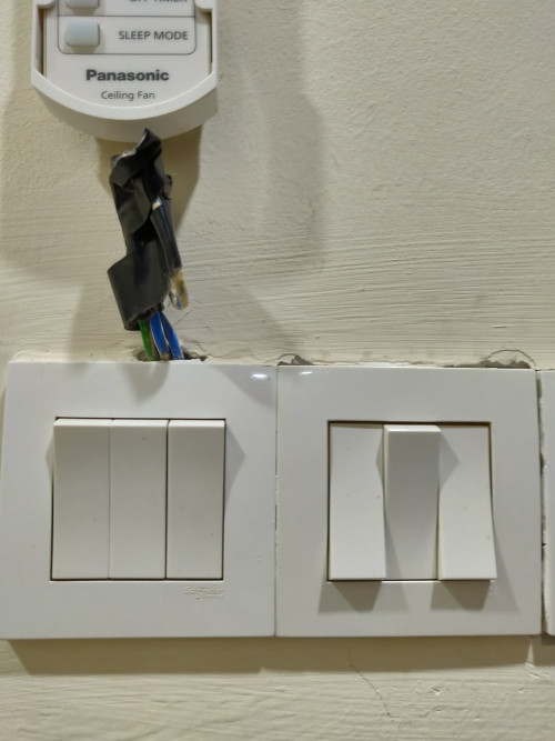
There's green and blue wire that was meant for fan regulator if I'm not mistaken protruding from nearby switch you can see then in the 2nd photos. Can I use them. I think one of the wires should be neutral right?
Fan regulator does not need N also. Probably they pull green for regulator grounding for safety. Blue is normal color for one of the phase.
I'm planning to install xiaomi 2gang wall switch on my house as it is under renovation now.
Focusing on 3 area which is car porch(4button), living hall(7button), (6button and this 3 area already took 9 units 2 gang switch.
However, it would cost a lot if i replace it with all the traditional switch. Can i know how you guys plan on this?
Since you are doing renovation now, get the contractor to pull the N wire as well. Even if you have no budget to replace the switches now, you can replace one by one when you have budget.
thanks for the reply but for devices that need to be switched on all the time especially the smart bulbs? even though they can be turned off from the app, the switch is still on and those bulbs are actually on standby mode rather than actually switched off.
Just like your TV, air-con and many other stuff on remote, never really off. You can read spec on power consumption during standby. I'd say all modern stuff consumed less than 1W. Probably in region 0.2~0.3W
guys, wanna ask the sonoff basic can act as a driver? example those downlight that we have got 1 driver (i presume that driver is convert ac to dc).
so can use sonoff replace that driver?
sorry just some noob question.
Why would you want to do that. What is you are trying to do?
Depends on what you meant by driver. I'd say LED driver is more than just convert AC to DC. AC to DC conversion is just a DC power supply. LED driver will also regulate current.
coz downlight driver (led) spoil. so wonder sonoff basic can act as driver as well.
so guess have to get the driver la.
Better and much much smaller than sonoff. Sonoff runs on 5V DC but if you connect to LED, it may blow the LED light even if it was running on 5V driver. LED driver is mostly like constant current source, where current supplied to LED is regulated to same amount no matter how many LED you connect in parallel for example. Regular power supply is constant voltage source.
so current go to sonoff then go to driver then go to downlight. this route correct? or current > driver > sonoff > downlight?
I don't understand. Sonoof is just a switch that can be managed suing WiFi. It runs on AC supply 240V. Basically it will act like a switch. The circuitry in Sonoff is running on 5V DC supply. That's all.
So, when you have down light, Sonoff will switch ithe downlight on and off. The supply to downlight is from AC supply (with built-in driver for sure) and has nothing to do with Sonoff.
Should be 3.3V for the ESP chip. Can't find a 5V source on the Sonoff Basic. You don't expect to connect the main voltage to your computer without the PSU, don't you?
that video the black and red put at L or N also no issue? also the wire from source of power also 2 wire, plugin any L or N in sonoff also no issue?
That video use Red and Black for L and N respectively. Usually the Red (+) and Black (-) is used for DC circuit. Your driver use Brown and Blue> Brown is for L and Blue is for N normally used in Europe (UK of course)
Blue - N Brown - L1 for 1 phase wiring
In 3 phase wiring Brown - L1 Black - L2 Gray - L3
Old UK standard is Black - N Red - L1 Yellow - L2 Blue - L3
US use White - N Black - L1 Red - L2 Blue - L3
Even if you connect the other way around in general it will work but follow standard for safety.
Anyone here using Home Assistant and Maxis Fibre? I just switch from Unifi to Maxis Fibre and I can't open HA port. Is it because of Maxis private Ip they provided? Thanks.


 Jul 10 2019, 10:23 AM

 Never seen you post something regarding any Smart device you have. Inb4 smart device is inside your brain.


 Quote
Quote


 0.3495sec
 0.31
0.31
 7 queries
 GZIP Disabled