

PC Audio Creative GigaWorks S750 7.1 speaker repair, A short guide and info with pictures...
|
|
 Mar 1 2016, 09:14 PM Mar 1 2016, 09:14 PM
|

Junior Member
10 posts Joined: Feb 2014 |
with this problem is there any chance that Bash sta575 failed ? or i have to replace it ?
|
 Quote
Quote|
|
|
|
|
Mar 4 2016, 08:31 AM
|
|
Junior Member
10 posts Joined: Feb 2014 |
QUOTE(dlduscg @ Oct 10 2015, 10:20 AM) Hi, I received your email and found your photo of the board and located C5. I see that you destroyed the cap and that there is no hope to recover and replace it. Also that there is no information on the same cap on my board that can offer any help to determine the value of the cap. First I would try to clean up the area and remove any of the old cap fragments that are still attached to the board. Then when you finish the glue removal and put everything back together, power up and find out what you have working/not working especially checking the inputs/outputs of the board. You may also try replacing the removed cap with a leaded cap; a small leaded wafer/paper cap .1 mfd 50v non polarized or one of your choosing to test for its effect upon the outputs. If you don't think you can work with SMT soldering techniques then just leave it for now or until you can find someone to do it. The important thing is to be sure that there are no pieces left from the damaged cap that would short out the circuit or allow a path for dc current to flow into other parts of the circuitry. hey man i need ur help please help me !! i really get feel so bad i really want to fix my speaker system . so please at least let me know u r still there ! check my posts here .The glue still on the board shown in your photo does not look degraded or necessary for removal. I do not know the condition of the whole board, but if all the glue appears the same, then I would not attempt any more removal on this board to avoid further damage to the board. The only glue that requires removal is the darkened, yellow or dark brown and/or spotted. If the glue is white and looks clean like what it appears to be in your photo, I would leave it alone. I don't know if this helps much, but it is going to be hard to determine what impact this cap will have on the overall audio operation of the speaker system, if any, until you have everything else up and ready to go, especially the main power supply.  |
|
|
Mar 17 2016, 11:49 PM
|

Newbie
4 posts Joined: Mar 2016 |
Thank you Lex, your post were very informing and helped me alot!
My S750 broke 3 days ago. Standby won't turn on. Green LED flickerin. Two years ago this happend the first time. But I left the S750 alone without power for a month in my cold apartment. After it warmed up and had power for several hours it turned back on again. This only happend 3 times in the last two years. But this time, it was warm and the S750 had power, it even was in standby but when I pressed the power button on the controller it broke down, the LED began to flicker and nothing happened. I searched the internet for tutorials and help. This posts were the best I found. I never had anything to do with electronics. I studied biochemistry and computer science so I am not total new to this, but I never learned electrical engineering. First I learned how to read the circuit diagram. Then I learned how the different components work. I disassembled the entire unit and took a good look. Then I started cleaning everything, and removing the old glue. It was all over the place. I started with the big capacitors, desoldering and measure resistance and capacity. But although my S750 is almost 10 years old, all seems to be fine, no visual damage or any bulging capacitors. Next I tried a cold heat method i read about. In order to find the numb capacitor. In my case it is C62, it was hidden underneath a shrinking tube (why??). First I though it has to be light proof, but it's just a normal capacitor. When I cool this one down, the LED keeps flickering, but if I heat it over 35°C it starts  As chemist I know reaction speed doubles each 10°C (10 K) I just order almost any capacitor on the board, but higher quality, Panasonic, Nichicon and Würth Elektronik (a german brand) from Conrad.de a german electronics shop, for around 40€. They should arrive tomorrow, then I will start replacing everything and start testing When it's done, I will write a short summary with pictures. |
|
|
Mar 18 2016, 01:58 AM
|
|
Newbie
4 posts Joined: Mar 2016 |
This is how it started.
http://imgur.com/wEm8U0m http://imgur.com/ImVWDHM Finding the numb cap. http://imgur.com/snHfytg Trying to power it up with all connected http://imgur.com/I0kisJi It worked  Start of desoldering http://imgur.com/IhPOxHL http://imgur.com/dMb37Fg Already removed a lot of old glue http://imgur.com/Je0hdTJ http://imgur.com/EKDVh2j These caps I removed today, new will come tomorrow If it works, I might change all caps but right now I am too lazy  http://imgur.com/HiixKFl Most look still good http://imgur.com/jFUQP8b http://imgur.com/bvlm48J The big 470 µF 200 V were at ~430 µF but I think this is still fine, one of them lost his "hat" ^^ The small one on the left looks good but I know that it's dumb : / My quick sketch http://imgur.com/56LVVrH All images will stay in my One Drive https://onedrive.live.com/redir?resid=D0D96...nt=folder%2cpdf |
|
|
Mar 19 2016, 02:59 PM
|
|
Newbie
4 posts Joined: Mar 2016 |
I removed all old capacitors and cleaned of the old solder
I tried to remove more old glue, but I am pretty sure I already removed it from places that could cause shorts http://imgur.com/SiORYIC http://imgur.com/HLXf24E And in these pictures you can see the new caps Except those 2 330 µF 100V the new ones didn't arrive  But they are very easy accessible from the outside, so I put everything back together and tested its function http://imgur.com/EDf7JIg http://imgur.com/ekhqsAl http://imgur.com/rNnoIlI http://imgur.com/f52QSFF http://imgur.com/9YYm8NL These 4 470 µF 200V are a little high 40mm old were 35 mm but there is still some headroom left New ones are Nichicon VY And like all I choose 105°C Works great now Starts immediately and no problems I think those 2 330 µF 100V will arrive at Monday http://imgur.com/xlRVUoq I am very glad that everything went out this well, it took me 5 days to learn what was going on and what to do On Monday it will be an entire week after first total fail until repair In the best case I will be able to use this system for another 20 years now Thank you all and especially Lex!! |
|
|
Mar 22 2016, 07:45 PM
|
|
Newbie
4 posts Joined: Mar 2016 |
Today I installed the new 330 µF 100V caps.
As predicted it were fairly easy without removing the psu board http://imgur.com/kWncvAy http://imgur.com/BIvabe0 I am done now, if there are any questions, I will try to help, but I am no expert Good luck to all of you! |
|
|
|
|
|
May 17 2016, 12:32 AM
|
|
Newbie
2 posts Joined: May 2016 |
Good Day all
I followed the steps in the whole forum to repair and upgrade my S750 surround system but it didn't work my problem wasn't directly with the power board, when my speakers started to die I turned it on one day then I heard sound of something exploding, then the sounds turn lower and the right channel was buzzing after that day my sound system always turns on but have this buzzing sound problem. after reading what's written I decided to upgrade the whole components, I checked on the power board, it seems to be OK, no fat Capacitor or burned Diodes or exploded stuff, but I noticed the two Capacitors on the Amp Boards in sector C40 blown and burned. what I did that I changed most of the parts in the power supply board then some capacitors in the amp boards according to this list (founded earlier in the forum) https://onedrive.live.com/redir?resid=E2DDC...int=file%2cdocx - First Repair Results: power on functioning correct and nothing exploded, but there's no sound at all from any speaker out !!  - Possible causes: 1 - some soldering points where so fragile, I may have cut/ruined the copper connections down some components on the power board within soldering? 2 - other contact point on the amp board where visibly damaged because of the hot soldering and I tried to fix them, but I got the same results (that didn't encourage me to continue replacing the capacitors in the amp boards) - Reviewing and Checking for any possible Visible problems: re-check on every soldering points, cable connections... no visible harm, nothing more to do !!  Please Help me find what to do else to complete this mess, I'm so disappointed and exhausted from trying to find the problem with no results regarding that I spent 120 euros to buy the components and feeling useless unlucky. I can uploads photos for every thing I solder on the boards, please tell me what to do  Thanks Homer This post has been edited by OE DarkThrone: May 17 2016, 12:45 AM |
|
|
May 17 2016, 11:33 PM
|
|
Junior Member
68 posts Joined: Apr 2015 From: China |
QUOTE(OE DarkThrone @ May 17 2016, 12:32 AM) Good Day all Since currently there's no schematics of amplifier board, maybe you need send to professional to repair.I followed the steps in the whole forum to repair and upgrade my S750 surround system but it didn't work my problem wasn't directly with the power board, when my speakers started to die I turned it on one day then I heard sound of something exploding, then the sounds turn lower and the right channel was buzzing after that day my sound system always turns on but have this buzzing sound problem. after reading what's written I decided to upgrade the whole components, I checked on the power board, it seems to be OK, no fat Capacitor or burned Diodes or exploded stuff, but I noticed the two Capacitors on the Amp Boards in sector C40 blown and burned. what I did that I changed most of the parts in the power supply board then some capacitors in the amp boards according to this list (founded earlier in the forum) https://onedrive.live.com/redir?resid=E2DDC...int=file%2cdocx - First Repair Results: power on functioning correct and nothing exploded, but there's no sound at all from any speaker out !! - Possible causes: 1 - some soldering points where so fragile, I may have cut/ruined the copper connections down some components on the power board within soldering? 2 - other contact point on the amp board where visibly damaged because of the hot soldering and I tried to fix them, but I got the same results (that didn't encourage me to continue replacing the capacitors in the amp boards) - Reviewing and Checking for any possible Visible problems: re-check on every soldering points, cable connections... no visible harm, nothing more to do !! Please Help me find what to do else to complete this mess, I'm so disappointed and exhausted from trying to find the problem with no results regarding that I spent 120 euros to buy the components and feeling useless unlucky. I can uploads photos for every thing I solder on the boards, please tell me what to do Thanks Homer My self-repair caused a short circuit when power on -- one of capacitor on amplified board was reversed when I soldered it, oops. Luckily, nothing damaged except the fuse. But it took me 1 year to find the problem (yeah, 1 year, leave it on the ground with dust on it until now I decided to repair it again). |
|
|
May 18 2016, 12:57 AM
|
|
Junior Member
68 posts Joined: Apr 2015 From: China |
Thanks @lex for this amazing helpful post which survived my S750!
I still have some small issues: 1. My bad, I muted center/subwoofer channel by mistake. I use pulseaudio in Linux operating system, however the center/subwoofer channel is muted in alsamixer: 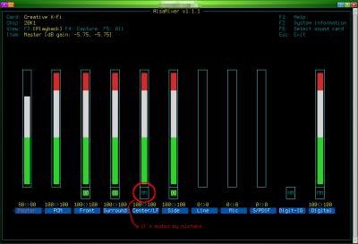
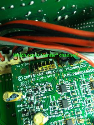
2. When tune volume + - or mute/unmute or power on to standby, there will be a noise come out of rear speakers (especially rear right speaker). and the volume of noise follows the main volume. 3. There was one time before: after plugged earphone into the jacket on remote control pod, sound still come out from speaker. But now I can't reproduce this issue anymore. About issue 1 and 2 and 3: There were massive glues on audio I/O board before, so I scratched them very carefully for several days, but still, there're glues under chips or between chip legs which I can't clean them all. Could this be a reason caused issue 1 & 2 & 3? Massive glues on audio I/O board 
4. The common issue: when power on, power go off automatically and then return to standby state. -- I'll leave this issue there, since it's not too annoying. 5. Occasionally, there's no sound of the relay after power on button is clicked -- so no power. The LED light on subwoofer is steady green, after clicked standby/power button, the LEDs on remote control pod are green too, it's seems power is on, but I can't hear the sound of relay. This post has been edited by asenrzhang: May 23 2016, 09:10 AM |
|
|
May 25 2016, 02:44 AM
|
|
Junior Member
5 posts Joined: May 2016 |
Hello while I was scraping the conducted glue I scraped off the green layer like in the imageσ below. Also the pads are gonners and I made some with your methods... Can you please tell me if I am doing something wrong or if I will have problem without the green layer cause i i tried to turn on the system and i saw a flash. You can see the blown part on the white surface in the 1st image.
This post has been edited by Jjk86: May 25 2016, 08:09 AM Attached thumbnail(s) 


|
|
|
May 25 2016, 05:31 PM
|
|
Junior Member
68 posts Joined: Apr 2015 From: China |
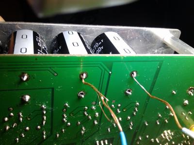
QUOTE(Jjk86 @ May 25 2016, 02:44 AM) Hello while I was scraping the conducted glue I scraped off the green layer like in the imageσ below. Also the pads are gonners and I made some with your methods... Can you please tell me if I am doing something wrong or if I will have problem without the green layer cause i i tried to turn on the system and i saw a flash. You can see the blown part on the white surface in the 1st image.  Even as an amateur, I can tell that's totally wrong: you'are connecting '+' to '-' which definitely made a short circuit. That's why you saw a flash (I made a similar mistake too - I reversed one capacitor). The 'L' connector should only made for the '-' leg/pin/hole of C59 C60 C69 C70 and the '+' leg/pin/hole of C61, because these legs/pins are connected on this side. 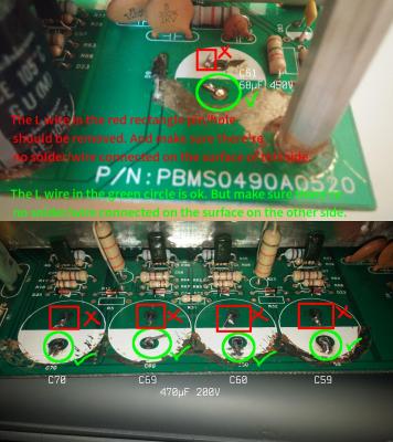
 And the 'L' wire should be better facing the other hole/pin, because the distance between capacitor legs/pins is a little wider which leave spaces inner side. See my wiring below: 
This post has been edited by asenrzhang: May 26 2016, 10:21 AM |
|
|
May 25 2016, 08:22 PM
|
|
Junior Member
5 posts Joined: May 2016 |
QUOTE(asenrzhang @ May 25 2016, 12:31 PM) Even as an amateur, I can tell that's totally wrong: you'are connecting '+' to '-' which definitely made a short circuit. That's why you will saw a flash (I made a similar mistake too - I reversed one capacitor). The 'L' connector should only made for the '-' pin of C59 C60 C69 C70 and the '+' pin of C61, because these pins are connected on this side.
http://img.vim-cn.com/fd/32ef3dc7a80e2ca70...8d21746a3fc.png And the 'L' wire should be better facing the other hole/pin, because the capacitor pin is a little wider which leave spaces inner side. See my wiring below:
Thank you asenrzhang for your answer !
Unfortunately the back of my pcb doesnt have any pads also how can i connect the capacitors on the back on the down side? Is there a chance my capacitors are blown now due to the short circuit? |
|
|
May 25 2016, 10:59 PM
|
|
Junior Member
68 posts Joined: Apr 2015 From: China |
QUOTE(Jjk86 @ May 25 2016, 08:22 PM) Unfortunately the back of my pcb doesnt have any pads also how can i connect the capacitors on the back on the down side? If you mean the pad around '-' leg of C59 C60 C69 C70 and '+' leg of C61 on the down/back side, then it is not a big issue. If you see carefully on my last photo, the pads are missing too (thanks for my bad soldering skill)For me, I just put lots solder on it (but DO NOT connect it to the copper surface around), and make a small globe which can make the capacitor more steady. I'm going to put glues on the capacitor to make it more steady. QUOTE(Jjk86 @ May 25 2016, 08:22 PM) Is there a chance my capacitors are blown now due to the short circuit? I can't tell. But you may want to check the fuse first. Then check these capacitors using a multimeter.My mistake caused 3-5 fuses blown, but the capacitor survived (Nichicon capacitors seems so damn good). My mistake is I soldered a new capacitor on the left amplifier board - the big one, the 1000μF one, but it's reversed. But after several fuses blown, this capacitor is still working. This post has been edited by asenrzhang: May 25 2016, 11:18 PM |
|
|
|
|
|
May 26 2016, 01:09 AM
|
|
Junior Member
5 posts Joined: May 2016 |
QUOTE(asenrzhang @ May 25 2016, 05:59 PM) If you mean the pad around '-' leg of C59 C60 C69 C70 and '+' leg of C61 on the down/back side, then it is not a big issue. If you see carefully on my last photo, the pads are missing too (thanks for my bad soldering skill) I just finished the soldering and modding of the solder pads and my s750 is working again For me, I just put lots solder on it (but DO NOT connect it to the copper surface around), and make a small globe which can make the capacitor more steady. I'm going to put glues on the capacitor to make it more steady. I can't tell. But you may want to check the fuse first. Then check these capacitors using a multimeter. My mistake caused 3-5 fuses blown, but the capacitor survived (Nichicon capacitors seems so damn good). My mistake is I soldered a new capacitor on the left amplifier board - the big one, the 1000μF one, but it's reversed. But after several fuses blown, this capacitor is still working. . Thank you for everything you have been a BIG help! There is only one problem though... My bass is not woriking as it was. It is not making loud bass sound, almost not hearing it at all sometimes and i need to enable the bass boost option on my sound card and when i disable the bass rederection i hear bass sounds from the surround speakers...    This post has been edited by Jjk86: May 26 2016, 01:10 AM |
|
|
May 26 2016, 01:51 AM
|
|
Junior Member
68 posts Joined: Apr 2015 From: China |
QUOTE(Jjk86 @ May 26 2016, 01:09 AM) I just finished the soldering and modding of the solder pads and my s750 is working again I have similar issue too, but not on the subwoofer / bass channel. It's volume of the Side Left and Side Right and Rear Left channels are a little bit lower.. Thank you for everything you have been a BIG help! There is only one problem though... My bass is not woriking as it was. It is not making loud bass sound, almost not hearing it at all sometimes and i need to enable the bass boost option on my sound card and when i disable the bass rederection i hear bass sounds from the surround speakers... Do you follow the guide in #7 post of this thread? I actually bought sandpapers to make the pins shining. 
Also, I scratched glues on the audio I/O board too. I suspect those massive degraded glues on audio I/O board may caused my issue, but I'm not sure, it's out of my skills.   This post has been edited by asenrzhang: May 26 2016, 02:06 AM |
|
|
May 26 2016, 02:14 AM
|
|
Junior Member
5 posts Joined: May 2016 |
Hmmmm ok i will try this method mate, although i have never touched the woofer and it was working perfectly till the system started doing the blinking green power light. I will dismantle it and i will try to remove this massive glue on the pcb. Thank you again for your help.
This post has been edited by Jjk86: May 26 2016, 02:18 AM |
|
|
May 26 2016, 04:34 AM
|
|
Junior Member
5 posts Joined: May 2016 |
I just cleaned most of the degraded glue on the sound I/0 pcb and checked on the subwoofer for any problems but i found none. The strange is in CMSS-3D option of the sound card program, if i enable it or no i see no difference and if i raise the bass % from 50% to 100% i hear more bass coming from the satellites instead of the subwoofer and the sound is becoming way too bad...
This post has been edited by Jjk86: May 26 2016, 04:40 AM |
|
|
May 26 2016, 12:15 PM
|
|
Junior Member
68 posts Joined: Apr 2015 From: China |
QUOTE(Jjk86 @ May 26 2016, 02:14 AM) Hmmmm ok i will try this method mate, although i have never touched the woofer and it was working perfectly till the system started doing the blinking green power light. I will dismantle it and i will try to remove this massive glue on the pcb. Thank you again for your help. QUOTE(Jjk86 @ May 26 2016, 04:34 AM) I just cleaned most of the degraded glue on the sound I/0 pcb and checked on the subwoofer for any problems but i found none. The strange is in CMSS-3D option of the sound card program, if i enable it or no i see no difference and if i raise the bass % from 50% to 100% i hear more bass coming from the satellites instead of the subwoofer and the sound is becoming way too bad... Sorry, my bad. I didn't make it clear, you may not need to check on the woofer speaker. I didn't mean the woofer issue, but only mean "More problems - sound channel randomly goes off" section in #7 post, and the degraded glues on audio I/O board.To be more clear, I'm talking about make these pins shining as @lex did:  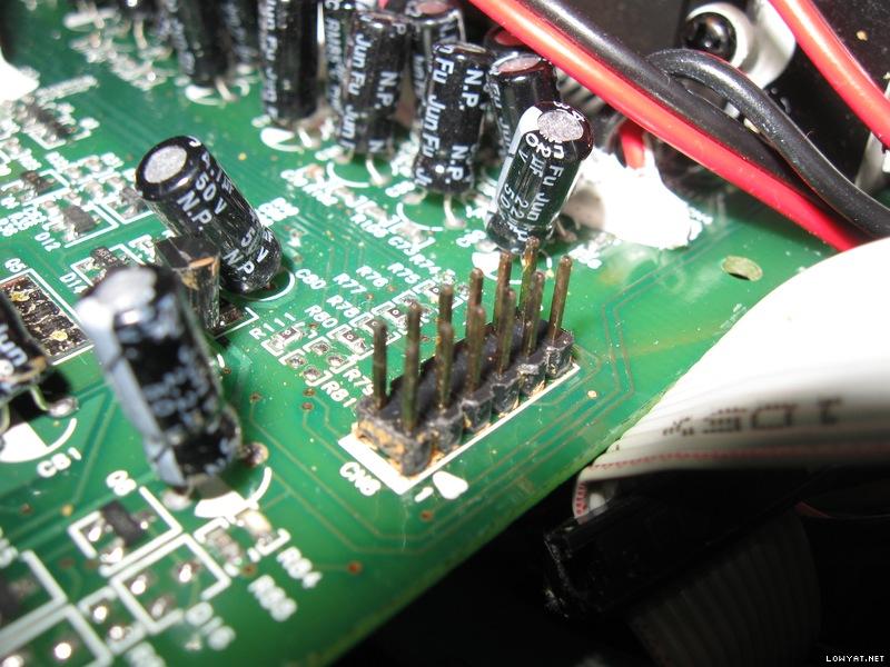 There're 3 set of these pins, one on audio I/O board, one on power amplifier board 1, one on power amplifier board 2. This post has been edited by asenrzhang: May 26 2016, 04:41 PM |
|
|
May 26 2016, 01:16 PM
|
|
Junior Member
68 posts Joined: Apr 2015 From: China |
--delete--
This post has been edited by asenrzhang: May 26 2016, 01:22 PM |
|
|
May 31 2016, 09:42 PM
|
|
Junior Member
68 posts Joined: Apr 2015 From: China |
QUOTE(asenrzhang @ May 18 2016, 12:57 AM) ... Now, it's dead again on issue 5 -- power LED & POD LEDs are ok, but it's just no sound came out. But sound came out from the right channel of earphone if I plug the earphone to POD, the left channel of earphone has very very low sound (nearly quiet, I must increasing the volume to hear it).5. Occasionally, there's no sound of the relay after power on button is clicked -- so no power. The LED light on subwoofer is steady green, after clicked standby/power button, the LEDs on remote control pod are green too, it's seems power is on, but I can't hear the sound of relay. This symptom remind me I had same issue after I bought this speaker for just one week, I posted my issue on official creative forum, but no solution. Here's my post on forums.creative.com 7+ years ago: http://forums.creative.com/showthread.php?t=506230 But this time, since I already fixed power supply board issue (I think so, because the power output to power amplifier board seems ok. Although I don't know how much voltage reading is good, but it's as same as the voltage reading when this speaker been revived), I suspect it's something wrong on power amplifier boards or audio I/O board. After I powered on for some time (perhaps half an hour), then power off, I touched the heat sinks -- the heat sink on power supply board is warm, but the heat sinks on two amplifier boards are not warm, so how to check which component on power amplifier board caused this issue (no visual damage)? =============== by the way, the voltage output readings of some connectors: CODE CN5 (to power amplifier board 2) ================================================== . . . . [.]RED |<------ 85.5v -------->| |<---- 18.7v ---->| |<--24.1v-->| |48.7v| |<---- 36.8v ---->| |<--61.4v-->| |66.8v| ================================================== CN4 (to power amplifier board 1) almost as same as CN5 CN6 (to audio I/O board) ================================================== . . . (0) . . . [.]RED | | | | | | | | 0v 4.3v 8.9v 0 12.2 -7.9v 0 8.9v ================================================== And the voltage reading between two legs of each 330μF/100V capacitor is 66.6V. This post has been edited by asenrzhang: Jun 6 2016, 02:07 AM |
| Change to: |  0.6055sec 0.6055sec
 0.73 0.73
 6 queries 6 queries
 GZIP Disabled GZIP Disabled
Time is now: 14th December 2025 - 01:38 AM |
All Rights Reserved © 2002- 2025 Vijandren Ramadass (~unite against racism~)
Powered by Invision Power Board © 2025 IPS, Inc.