

Scotty, what about the old thread? It still contains useful informations for newbies.
DIY DIY amp club V2, Post your DIY amp here
DIY DIY amp club V2, Post your DIY amp here
|
|
 Jan 16 2009, 01:25 PM Jan 16 2009, 01:25 PM
Return to original view | Post
#1
|
 
Senior Member
4,234 posts Joined: Nov 2004 |
Scotty, what about the old thread? It still contains useful informations for newbies.
|
|
|
|
|
|
Jan 16 2009, 10:50 PM
Return to original view | Post
#2
|
|
Senior Member
4,234 posts Joined: Nov 2004 |
QUOTE(MadCow @ Jan 16 2009, 10:39 PM) Guys, if u dont mind me interrupting. A lengthy process, takes bloody much time, but the effort is worth it.How do u cut a say 3 inch hole? I use to DIY myself but the outcome aint always nice. I'm thinking of DIYing a SOHA II but I'm having difficulties drilling 2 holes on the top of the casing for the tubes.  Use masking tape to mask the area you want to drill. Draw a sketch of the circle on it. Proceed by drilling lots of lots of holes using the largest drill bit available exactly within the area to clear it out. File the rest of the tiny bits to get a nice circle. It's time consuming due to the need to drill multiple times. EDIT: Alternatively, a dremel works with the above method too, except faster. This post has been edited by LittleGhost: Jan 16 2009, 10:52 PM |
|
|
Jan 18 2009, 11:28 PM
Return to original view | Post
#3
|
|
Senior Member
4,234 posts Joined: Nov 2004 |
^Plus and minus.
In short, shunt regulator has ugly efficiency compared to the series regulator. In general, shunt is used widely for isolation purposes and for local regulation when the current draw is not too big while series for global regulation (providing a huge block of circuits which draws higher current). Shunt does have some benefits over series regulator: 1) Protected against input transients (isolation feature) 2) Current output is limited by CCS, thus no explosion due to shorted outputs. 3) To a certain extent's better than the series regulator due to symmetrical current sinking and sourcing. For your case, you'll do fine with both solutions. Alternatively, use the super fast Jung Super Regulator to beat the crap out of both solutions. |
|
|
Jan 19 2009, 08:37 AM
Return to original view | Post
#4
|
|
Senior Member
4,234 posts Joined: Nov 2004 |
^switching can be prevented by forcing the regulator output to light Class A.
|
|
|
Jan 20 2009, 08:29 AM
Return to original view | Post
#5
|
|
Senior Member
4,234 posts Joined: Nov 2004 |
QUOTE(ccschua @ Jan 19 2009, 11:47 PM) how do you do that and with what mod ? actually, diode transients are negligible if your PSU is done right. Adding the snubber caps already eliminate most of the noises. In addition, your main circuit must have already high PSRR so it does not even matter at all. (if it doesnt have high PSRR it's not worth it anyway)Sometimes, back EMF can cause the regulator to "momentarily" switch down. If there's enough capacitance on the output, this is usually not an issue. Performance can be further improved by forcing a constant current out of it, e.g. using an LED. |
|
|
Jan 20 2009, 04:35 PM
Return to original view | Post
#6
|
|
Senior Member
4,234 posts Joined: Nov 2004 |
mlm <--- behold my finger of jealousy.
Anyway, I just pulled the trigger on three B22 boards and one s22 board. Oh noes, sins!!! |
|
|
|
|
|
Jan 20 2009, 10:33 PM
Return to original view | Post
#7
|
|
Senior Member
4,234 posts Joined: Nov 2004 |
Build some discretes like the Hiraga and let me know if your opinions change.
 |
|
|
Jan 21 2009, 06:35 PM
Return to original view | Post
#8
|
|
Senior Member
4,234 posts Joined: Nov 2004 |
First time etching my own PCB.
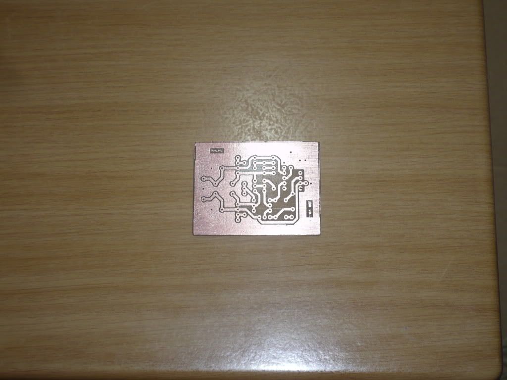 EDIT: A JFET based Class A buffer with servo control. Planning to use it for my balanced setup/just stereo buffering. This post has been edited by LittleGhost: Jan 21 2009, 06:37 PM |
|
|
Jan 21 2009, 08:52 PM
Return to original view | Post
#9
|
|
Senior Member
4,234 posts Joined: Nov 2004 |
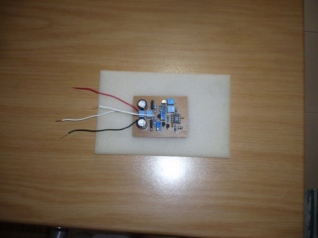
took me 3-4 hours just to get it right O_O"
Semi populated the board. Not sure if i want to heatsink the output transistors and bias them further.  . Lazy, will continue testing and debugging tomorrow. . Lazy, will continue testing and debugging tomorrow. |
|
|
Jan 25 2009, 03:57 PM
Return to original view | Post
#10
|
|
Senior Member
4,234 posts Joined: Nov 2004 |
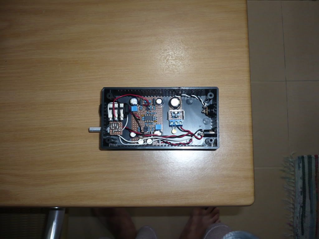
 Tested and assembled. Did no hearing test yet, but I'd assume it to be pretty good sounding. Basic Buffer application for pre amps or directly driving headphones. It's ac coupled so sources can do away the output caps. EDIT: Next thing will be a dual rail PSU and a discrete amplifier This post has been edited by LittleGhost: Jan 25 2009, 03:57 PM |
|
|
Jan 30 2009, 08:38 AM
Return to original view | Post
#11
|
|
Senior Member
4,234 posts Joined: Nov 2004 |
QUOTE(valve_300b @ Jan 30 2009, 02:13 AM) if you get ur design right, i don't see the need of Thevenin Theorem. Perhaps noob will need it cause they might be too good in talking technical but can still get the calculation wrong I lol'd IRL.  Small signal and large signal analysis, hybrid models and such. If your design doesnt revolve around around that, then it has failed. |
|
|
Jan 30 2009, 08:42 AM
Return to original view | Post
#12
|
|
Senior Member
4,234 posts Joined: Nov 2004 |
XD it will be an issue if he uses the 56.2k Ohm resistors.
The FETs have the best symmetrical swing with 50Ohm loading. |
|
|
Jan 30 2009, 11:01 AM
Return to original view | Post
#13
|
|
Senior Member
4,234 posts Joined: Nov 2004 |
Demanded PICTARS? Request delivered.
 This is an amp that i just finished for a forumer. Class A biased Diamond buffers with a dual opamp, plus a mini 12V regulator. Used quality components. 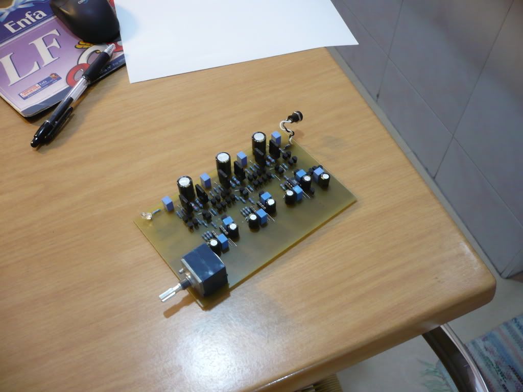 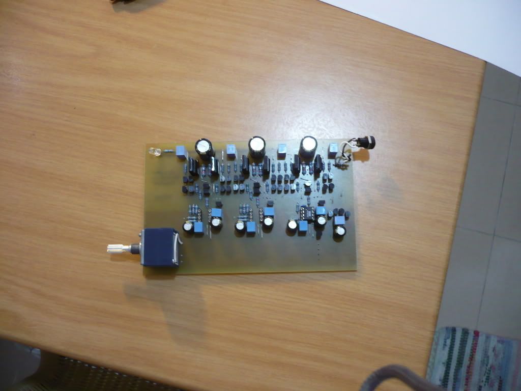 Also, pcb'ed dB3 amplifier (single layer) for prototyping. Etched myself using iron transfer. Planning to go fully factory manufactured PCB after I'm done tweaking it with an OPAMP that would beat even discrete stages. Capacitance multiplier seems great for isolation but I'm currently thinking of individual shunt regulators per OPAMP for greater isolation. Just finished populating it last night. Might do some listening tests later after I claim my RM600 for the road tax. lawl. Here are some other older pictures if anyone of you are interested:    My main amp . AD825 fully Class A amplifier.This post has been edited by LittleGhost: Jan 30 2009, 11:08 AM |
|
|
|
|
|
Jan 31 2009, 08:44 AM
Return to original view | Post
#14
|
|
Senior Member
4,234 posts Joined: Nov 2004 |
nay, i'm thinking off simple discrete shunt regulators instead of a single capacitance multiplier. A low noise BZXC series zener diode buffered by a low noise BJT. It really does not take up much space though. More like PPA's isolation JFET plus four more components per channel. IC Linear regs? XD I'd rather do 3 jungs and feed 3 separate channels. However seriously unnecessary lol. I'd be gone with fully discretes if I were to reach that point.
I've been hearing good words on the AD797BRZ (higher grade with very different specs comparing to the ARZ version). However it's bloody hard to implement properly due to it's insane speed. Not to mention input bias is high due to it's BJT input. Planning to build an amp that revolves around that chip and properly bypassed and compensated. I've had that gut feeling that the Input transistors of the diamond buffer plays the most significant role in that topology. Hence why the use of very high impedance swap mirrors with feedback to load the input transistors. Sounds better than a regular PPA buffer. Thinking of further cascoding the input transistors. I guess I'll have to sim moar to proof that the most significant influence comes from the input transistors. |
|
|
Jan 31 2009, 10:46 AM
Return to original view | Post
#15
|
|
Senior Member
4,234 posts Joined: Nov 2004 |
not the same class
AD797 is way ahead of the OPA627, specs wise. |
|
|
Jan 31 2009, 01:29 PM
Return to original view | Post
#16
|
|
Senior Member
4,234 posts Joined: Nov 2004 |
Not necessarily.
Read the recent review from Majkel? He ranked the AD797 better than the OPAs from Audio-GD. HDAMs are kinda limited in some area due to space constrains. You cant lay additional parts for it. The AD797 is also an improved folded cascode topology which gives it insanely low distortion. (tip: the extra transistor on the floating mirror ) If you want to beat that you'll have to lay the entire amplifier circuit down instead and use as much performance enhancing designs as possible. |
|
|
Jan 31 2009, 02:58 PM
Return to original view | Post
#17
|
|
Senior Member
4,234 posts Joined: Nov 2004 |
Not only that. The AD797 hates driving capacitive loads too. Fortunately I'll be using a buffer along with it so it's not really an issue lol.
Just pray that it's not as worse as the AD8397. I don't want to use ferrite beads on mein signal. |
|
|
Feb 1 2009, 10:26 PM
Return to original view | Post
#18
|
|
Senior Member
4,234 posts Joined: Nov 2004 |
Empire23 is right. It hates driving capacitive loads like I've mentioned earlier. Adding output resistances will counter it but you kinda mess up the whole idea of a buffer (low Zo)
The AD797 is not cost effective. How about giving Amb's Jisbos a try? It's one of the best buffers around. |
|
|
Feb 1 2009, 10:38 PM
Return to original view | Post
#19
|
|
Senior Member
4,234 posts Joined: Nov 2004 |
The AD797 is a beast. I doubt the schematic's AD797 is properly implemented.
AD797 requires a lot of effort to tame it down and to sound good. Q1: yes it does have global feedback. Global feedback generally means the loop encompasses the entire signal path. Feedback point is taken from the end of the output. Q2:Schematic doesnt show the NE5534 |
|
|
Feb 2 2009, 08:31 AM
Return to original view | Post
#20
|
|
Senior Member
4,234 posts Joined: Nov 2004 |
Feedback is a good thing. But too much is bad. The feedback factor on opamps are generally high due to the very high open loop gain and the not so flat/linear open loop gain/bandwidth.
Another way to counter this is to use jung multiloop so you push the distortions due to feedback out of the audio spectrum. EDIT: Yes, the TDA is dc coupled. Caps however can be added in between stages for better effect. If the AD797 is stable, you can put a small high quality film cap between the DAC and the buffer instead to get more efficiency and signal quality. Since the input Z of the opamp is high, you don't need an electrolytic. This post has been edited by LittleGhost: Feb 2 2009, 08:33 AM |
| Change to: |  0.0462sec 0.0462sec
 0.34 0.34
 7 queries 7 queries
 GZIP Disabled GZIP Disabled
Time is now: 22nd December 2025 - 07:13 PM |
 Quote
Quote