QUOTE(vcheewei @ Aug 6 2021, 09:28 PM)
To all the pros out there, need ur advice again 😬😬😬
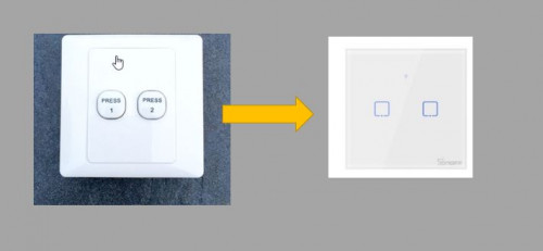
Having issue on replacing traditional switch to this smart switch.
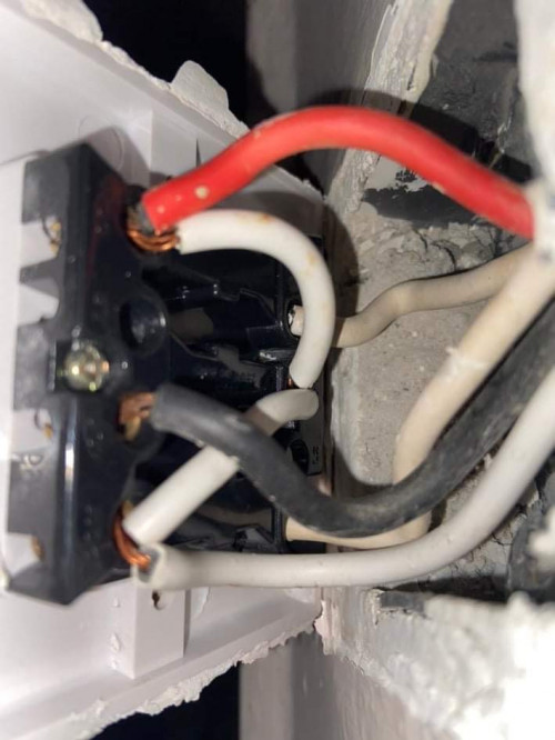
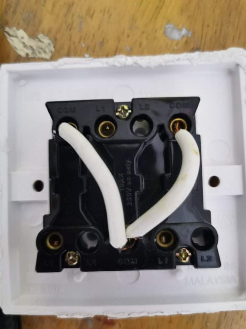
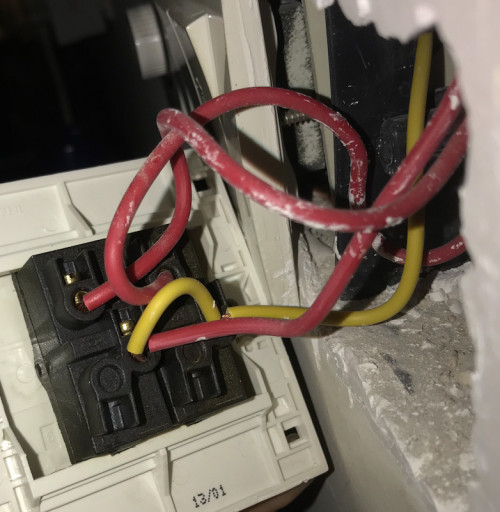
Clearer pic of the wiring on the old switch. Texted with testpen and only the red one light up.
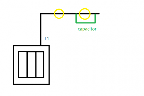
How to connect to this new smart switch as below:
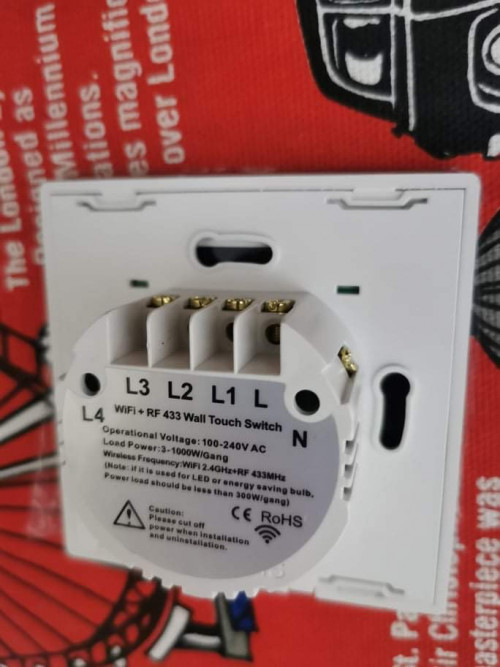
Do I need to put capacitor?
i looked back again at ur post.
seems got another live looping there (white cable #2)
so #1 and #2 need go in L smart switch.
the rest #3 #4 #5 is load.
» Click to show Spoiler - click again to hide... «
for our local switch, usualy no N or E at switch (except for 20A switch)
i hope u do have some basic knowledge or skill and safety precaution when doing DIY electrical works.


 Dec 20 2019, 11:46 AM


 Quote
Quote


 0.3031sec
 0.54
0.54
 7 queries
 GZIP Disabled