QUOTE(SubK002 @ Aug 17 2016, 05:56 PM)
I have 1 unit S750 faulty woofer, who wanna take it?

I'd like to buy a faulty subwoofer for backup.What's the symptom of your woofer? I need to know the symptom to see whether or not I can repair it.
PC Audio Creative GigaWorks S750 7.1 speaker repair, A short guide and info with pictures...
|
|
 Aug 17 2016, 11:46 PM Aug 17 2016, 11:46 PM
Return to original view | Post
#21
|

Junior Member
68 posts Joined: Apr 2015 From: China |
QUOTE(SubK002 @ Aug 17 2016, 05:56 PM) I have 1 unit S750 faulty woofer, who wanna take it? I'd like to buy a faulty subwoofer for backup.What's the symptom of your woofer? I need to know the symptom to see whether or not I can repair it. |
|
|
|
|
|
Aug 18 2016, 02:48 AM
Return to original view | Post
#22
|
|
Junior Member
68 posts Joined: Apr 2015 From: China |
 Disclaimer: I'm not a professional electronic engineer, not even an amateur, so, take the advice at your own risk. Disclaimer: I'm not a professional electronic engineer, not even an amateur, so, take the advice at your own risk.QUOTE(rsseco @ Aug 18 2016, 12:56 AM) So, I've check the resistance between 1&3 pin of D3, D5, D2 and D4. They are all conductive, with about 1 ohm ! Wait, what? all of them? That's my stupid mistake, they should be short circuited!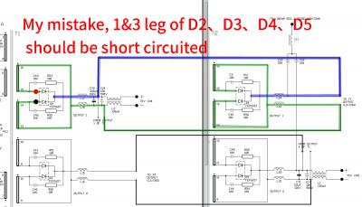
Change the measure method in this way: Switch multimeter to 'Diode' location, Red probe on leg 2, Black probe on leg 1 then 3. 
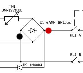
If they're conductive, then it's failed. (like testing normal diode.) QUOTE(rsseco @ Aug 18 2016, 12:56 AM) But... Where is D1 ??? If I remember correctly, D1 is here (see the picture)
But since there's no model name of this 6 AMP bridge rectifier on schematics, I don't know which two legs should be tested. This post has been edited by asenrzhang: Aug 18 2016, 02:53 AM |
|
|
Aug 18 2016, 06:16 PM
Return to original view | Post
#23
|
|
Junior Member
68 posts Joined: Apr 2015 From: China |
QUOTE(SubK002 @ Aug 18 2016, 05:52 PM) No power, I think power supply spoilt. Yes, I want a faulty S750 subwoofer toSure, you want?
I actually tried to buy one on eBay: http://www.ebay.com/itm/322228247729 , but the owner canceled my bidding since I'm a new guy (Zero Feedback) on eBay. By the way, does your subwoofer selled with other components? such as the Control Pod and/or the Remote Control and/or the audio input cable. I think I need at least a subwoofer and a Control Pod and audio input cable to make a 7.2 system. |
|
|
Aug 19 2016, 12:43 AM
Return to original view | Post
#24
|
|
Junior Member
68 posts Joined: Apr 2015 From: China |
Disclaimer: I'm not a professional electronic engineer, not even an amateur, so, take the advice at your own risk. QUOTE(rsseco @ Aug 18 2016, 11:18 PM) ... That could be capacitors absorbing power for a short time.Sometimes, only at first touch with the black leg, I've got a value, but only a fraction of second (then it shows it's non conductive) QUOTE(rsseco @ Aug 18 2016, 11:18 PM) Tested with component already soldered on board, I'd like to precise. D2~D5 are okay + each time Q3 Q4 got burned, these two phenomenons push my sight to the Gate side of Q3 Q4, my guess is some components in the marked area may failed, then make Gate-Source over voltage (Vgs limit is ±20V).OK, I've seen the inscription on the board, it was hidden by the heatshrink. I've tested this component too : red probe leg on the last (or first) pin, and black on each other pin : passive in one way only, 3 different values of resistance. And finally, I tested the two Q3 and Q4 : I confirm, they are out of order (conductive in all ways !) So, now what could be the matter ?  My guess could be totally wrong though. 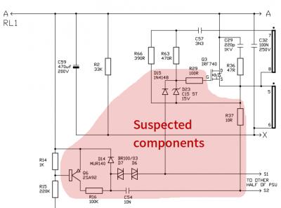
I don't know how to check D23 D6 D7 Q6, so you can check D14 D15 first (easy to check). QUOTE(rsseco @ Aug 16 2016, 11:29 PM) ... Your photos of Q3 Q4 been burned/cracked were taken from Gate side, so I don't know the situation on Source side, if Source side are not burned/cracked, it may proved that it's Vgs over voltage caused Q3 Q4 been burned/cracked.see pictures :   ... This post has been edited by asenrzhang: Aug 19 2016, 01:48 AM |
|
|
Aug 20 2016, 05:52 PM
Return to original view | Post
#25
|
|
Junior Member
68 posts Joined: Apr 2015 From: China |
Disclaimer: I'm not a professional electronic engineer, not even an amateur, so, take the advice at your own risk. QUOTE(rsseco @ Aug 19 2016, 02:53 AM) I begin to check some components : If resistor is not unsoldered, it's reading value is often smaller because of the parallel circuit.D14 is ok R14 have 980 ohm R15 value is always changing, and decreasing R37 have 5,9ohm instead of 10 ? R29 have 89ohm instead of 100 ? QUOTE(rsseco @ Aug 19 2016, 02:53 AM) For the rest, I must first remove the heatshrink, then I will remove the two Q3 and Q4 and will recheck all these values. QUOTE(rsseco @ Aug 17 2016, 04:24 AM) I re-check the specs of the IRF, they are designed for 400V, so as you say, it's not an over-voltage, as if the power value on this point not exceed this value ? After Q3 and Q4 been removed, can you power on again and check the voltage of following? Maybe your suspicion is right.
QUOTE(rsseco @ Aug 19 2016, 02:53 AM) Just to remember, at the origin of the default, only C70 has explosed/leaked, the 3 other caps were only "bombed". Will the problem not be on the "road" to it ? I couldn't tell. But you already replaced C59 C60 C69 C70 & C61 with new capacitors in same rating right?QUOTE(rsseco @ Aug 19 2016, 02:53 AM) And only one of the IRF740 was defective, why are they now 2 which brake down ? I couldn't tell either. Maybe one of them survived in the first time, and this time it had no luck. |
|
|
Aug 21 2016, 06:29 PM
Return to original view | Post
#26
|
|
Junior Member
68 posts Joined: Apr 2015 From: China |
Disclaimer: I'm not a professional electronic engineer, not even an amateur, so, take the advice at your own risk. QUOTE(rsseco @ Aug 21 2016, 02:57 AM) Ok, the only thing I will remove before runing this test, is only these 2 components ? Yes, because Q3 Q4 had been burned/cracked, so remove them in case they are short circuited.QUOTE(rsseco @ Aug 21 2016, 02:57 AM) When you write "power on", that's mean : replace fuse, power cord in (to AC outlet), main power switch on ? Or the same, incl. power on via control pad ? Power on via control pod: press the "standby/power" button to switch from 'Standby' state to 'Power On' state. This will give power to Q3 Q4 (well, actually, giver power to solder pads of Q3 Q4, it's open circuit now)QUOTE(rsseco @ Aug 21 2016, 02:57 AM) Is there no risk to blown the fuse again, despite Q3 and Q4 are left ? There's always a risk until all issues are cleared. If somewhere else than Q3 Q4 had been short circuited (degraded glues, or a piece of solder), it will make fuse blown too.Measure the voltage is just to clear the suspicion of over voltage. QUOTE(rsseco @ Aug 21 2016, 02:57 AM) The big caps are new, yes. The only thing which change compared to original, is they're 250V instead 200V. It's okay to me to use 250V rating instead of 200V.C61 is original cap (I don't know why I removed it...). You think it could be the faulty one ? C61 is used for standby part, so, it shouldn't affect the main power part. What I cared here is the original capacitors may not shape the waveform very well. =============================== QUOTE(rsseco @ Aug 12 2016, 02:57 AM) Today was THE day ! By the way, when you said "it's alive", do you mean you powered it on and listened some music? or just saw the standby LED is on in red color?And finally... it's alive again ! ... QUOTE(rsseco @ Aug 16 2016, 11:29 PM) ... Is the heat sink and mounting copper short circuited?Edit : I check Q3. It seems the "burn" comes from... - Q4 have split ! (between ceramic and the heatshrink) ... This post has been edited by asenrzhang: Aug 22 2016, 03:07 AM Attached thumbnail(s) 
|
|
|
|
|
|
Aug 23 2016, 03:05 AM
Return to original view | Post
#27
|
|
Junior Member
68 posts Joined: Apr 2015 From: China |
QUOTE(rsseco @ Aug 23 2016, 12:41 AM) Hi, I was a bit busy this week-end, so I haven't done the new tests yet. Thanks for your detail information!But I can answer some of your questions : I just hope I will not make more damage on the board/toanother components ! For degraded glue, I think there is no more on this power board. But on the others board, I didn't clean it. I will try to explain you as cleary I can, with my poor english ! For the story before this day, and in order to make the work easier, I removed the all electronic board from the subwoofer housing (the wood housing). And for do this, I desoldered the speaker (3x cables) So I had only the back plate with all board attached to it. And the power board wasn't screwed on this back plate. Before I found that Q3 or Q4 were brocken, at the time I replace the capacitors, I have done a test (as you ask me to do the last time) without the 2 dash amplifier board connected. So, coming to this D-Day : - I began to replace the capacitor at the same place as original (before, I "deport" them). On C61 and two of the "bigs", I had to do the "L" method with a short piece of cable, as I hadn't the ring on the back of the board. After the capacitors were on position, I checked if all the pole were conductive : they were (and it's at this time that I noticed I had a short circuit between a - pole of one cap to a + pole of another...) - After that, I screwed back Q3 and Q4 on the heatsink, and then I replaced the all thing on the board back. I first soldered back Q3 and Q4. After all was OK, I wanted to screw back the other Qx ... and it's a this moment that I didn't found the screws anymore. - So, in order to test the repair, I decided to take some screws with spacers from the uppers transitors (Dx ...) - I connected the PSU board on the "main" board (and that's it), connected only the control pod, replaced the fuse, checked if main switch is on 0 position and connected the power cable in the outlet. I check too if the 3 cables to the speaker aren't shortcuting. - Main switch passed on 1 : green LED on back plate : ON ; red LED on control pod : ON - Powered on via control pod : amber of master going ON and volume LEDs too ! I waited on this state 4-5 s (before, after max 2s the fuse blowned). So, as I had removed the screws from some transistors, I didn't want to wait on power on state for a while and switched it off. For me it was repaired at this time, as the fuse was already OK. It looks you had done perfect checks!  It could be better if you powered on for a longer time, say five minutes. QUOTE(rsseco @ Aug 23 2016, 12:41 AM) - The next day, I searched some screws with spacers (I dismantled a PC PSU to do so) and the evening I reassembled all back (I had soldered the speaker the day before). And as said, for me it was completly fixed, I didn't tryed it before and had closed the subwoofer with all screws, took it at place, connected the soundcard and all speakers cables and... powered on...1...2...off !!! The rest of the story, you know it ! So, there could be something happened in this step which caused fuse blown.QUOTE(rsseco @ Aug 23 2016, 12:41 AM) I have already checked this, on all Qx : no, they are isolated from the heatsink. I assumed that you did same check on D2~D5 too, am I right?QUOTE(rsseco @ Aug 23 2016, 12:41 AM) I check if any shortcircuit were between the two aluminium spacers which fastens the psu board on the L-aluminum plate : negative too (I thought it could comes from this, as my tests were done without this aluminum plate. If I remembered correctly, these two aluminum screw nuts are connected to GROUND on power supply board. |
|
|
Aug 24 2016, 02:44 AM
Return to original view | Post
#28
|
|
Junior Member
68 posts Joined: Apr 2015 From: China |
QUOTE(jsmars @ Aug 24 2016, 01:04 AM) ... 2 1189-1042-ND CAP ALUM 330UF 20% 100V RADIAL What I'm really wondering is, if you could check the list included in this post and see if I've added all the correct components and correct quantities, and if I'm missing any other ones that could be required for one complete repair job? I'm thinking I might as well replace all the old cheap brand capacitors so that these will last as long as possible when I've repaired both of them. I will order 2x the amounts ofcourse since I have two sets and probably a few extra of most of them just in case. My list can be seen directly at DigiKey by this link: http://www.digikey.se/short/3ht51q And here is the list in text: ... Okay, Rubycon ZLJ series is what @lex used as replacement. 1 478-5096-ND CAP CER 0.1UF 50V X8R RADIAL Okay, This is what @lex used as replacement. 10 100QBK-ND RES 100 OHM 1/4W 5% AXIAL I never replaced a resistor, so I don't know if it's okay. 1 IRF740PBF-ND MOSFET N-CH 400V 10A TO-220AB There're 4 IRF740 MOSFETs on PSU board, if you only need one, then it's okay. 10 A106002CT-ND RES 10.0 OHM 2W 5% AXIAL I never replaced a resistor, so I don't know if it's okay. 4 493-7851-ND CAP ALUM 470UF 20% 200V SNAP Okay, I bought exactly same part number as yours. 1 P13680-ND CAP ALUM 68UF 20% 450V RADIAL (Not sure about size of this one?) Height=42mm is little bit higher, the original one is about 30mm. What I bought is Nichicon UCS2W680MHD. 3 1189-1019-ND CAP ALUM 1000UF 20% 100V RADIAL (These might not be needed, but good for long life, correct?) This one is for two power amplifier boards. Size is okay. But it said it's for "General Purpose" application, I'm not sure if it's okay. What I bought is Nichicon UPW2A102MHD 5 UPM1V221MPD6-ND CAP ALUM 220UF 20% 35V RADIAL Height is a little big higher, but I think it's okay. But it's for "General Purpose" application, I'm not sure if it's okay. What I bought is Nichicon UHE1V221MPD6 2 493-1547-ND CAP ALUM 47UF 20% 25V RADIAL Size if okay. But it said it's for "General Purpose" application, I'm not sure if it's okay. What I bought is Panasonic EEU-FR1E470 ======= Looks like you forgot five 110μF 35V capacitors. I bought Nichicon UPW1V101MPD as replacement, not perfect, because it only has 3000 hours life. This post has been edited by asenrzhang: Aug 24 2016, 02:49 AM |
|
|
Aug 24 2016, 05:56 PM
Return to original view | Post
#29
|
|
Junior Member
68 posts Joined: Apr 2015 From: China |
QUOTE(rsseco @ Aug 24 2016, 05:08 PM) This night I thought about a thing I didn't tell before, because for me, it was "normal" (as I had this symptom often by the past) : Mine has this symptom too, one post in this thread said D6&D7 need to be replaced. I replaced them, but this does not fixed the issue.My S750 had this annoying "problem" (as said, before it does break and was working perfectly) on power on : often (not always) when I powered on the set via control pod, my set powered on and immediatly off. You could hear the relay "clicking twice" shortly. It's as I "double press" the button, but I didn't do. A new press powered it on "normally". After I repaired (also I thought it was repaired), it does the same thing on the first start... And if you read posts in this thread one by one, you may found others have same symptom too. I leaved this issue there, because I can still power on the woofer. By the way, let me gather the description said by others about this symptom
QUOTE(rsseco @ Aug 24 2016, 05:08 PM) But yesterday, as said, I powered it on 3 times, and never I had this symptom. Yes, it only happened on the first time, if you power off then on several times after that, it does not "reset" anymore.And what I found bizarre too, is after powering off/down, the relay takes longer to "click" (5 to 10s after red led is showing the off status). On power on, no problem, the relay clicks immediatly. I don't remember anymore if on power off it should do the same or not. Or, perhaps it's as Q3 or Q4 are left, so it takes longer ? If it can help... And yes, there's a delay to hear the 'click' sound (I guess it's the sound of relay switched to OFF position). What I'm guessing (just guess, and it could be totally wrong!!!) here is 1. When power is ON, capacitors may absorbing lots power, and make some other components can't get enough power? 2. The delay time of hearing the 'click' sound after power off, I don't think it's related to the missing of Q3 and Q4, it could be the capacitors still have remaining power to hold the relay at ON position. The following power off and then on actions does not trigger the "reset" symptom, could also because of the remaining power in capacitors. I mean they does not absorbing power hardly. This post has been edited by asenrzhang: Aug 25 2016, 02:18 AM |
|
|
Aug 24 2016, 07:39 PM
Return to original view | Post
#30
|
|
Junior Member
68 posts Joined: Apr 2015 From: China |
QUOTE(rsseco @ Aug 24 2016, 03:37 AM) ... I guess it could be/mean 'K' instead of 'V', maybe low half of 'K' is not visible or does not exists.I used the "sound" parameter to check shortcircuits, Diode for diodes, Ohm for resistors (and sometimes to check shortcircuits) and V continious for voltage. The Diod gaves me values in V... QUOTE(rsseco @ Aug 24 2016, 03:37 AM) So, here's a look of the board without Q3 and Q4 : I noticed you're using Rubycon MXR series. I checked the datasheet, found that it's height is 50mm, it's too high, that could make the top of capacitors too close to the heat sink. Or worse, it could touch the heat sink. Closer to Q3 And closer to Q4 
lex's second fix had shown this mistake made in the owner's self-repairing.  Also, I found something strange about the plastic wrapper of these capacitors
Maybe it's not a big deal, but I worried about their genuine. This post has been edited by asenrzhang: Aug 24 2016, 09:42 PM |
|
|
Aug 24 2016, 09:09 PM
Return to original view | Post
#31
|
|
Junior Member
68 posts Joined: Apr 2015 From: China |
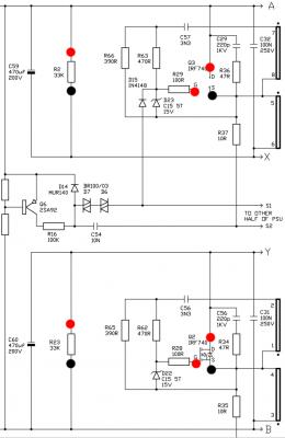
Disclaimer: I'm not a professional electronic engineer, not even an amateur, so, take the advice at your own risk. QUOTE(rsseco @ Aug 24 2016, 03:54 AM) Following results are without Q3 and Q4, PSU board alone (not connected) and no powered. I rephrased/rearrange your test results to make it simpler.= means conductive, or shortcircuit. Q3(S) = Q4(S) = C59(-)/C69(-)/C70(+)/C60(+) Q3(D) = Q4(D) = C59(+)/C69(+) Q3(G) -> Q4(G) = 1.19 kOhm Q3(G) : N/A to all +/- capacitors C70/C69/C60/59 Q4(G) : N/A to all +/- capacitors C70/C69/C60/59 Resistance between Q3(G) and Q4(G) is irrelevant here. ✓ Other results are as expected. QUOTE(rsseco @ Aug 24 2016, 03:54 AM) Values : D6 & D7 are DIAC, which I don't how to check it, but it should be non-conductive in both direction, as expected.- R37 : 5.1 Ohm - R29 : 98.1 Ohm - D6 : + -> - or - -> + : N/A - D7 : + -> - or - -> + : N/A - D14 : - -> + : 0.47V (conductive) / + -> - : N/A - R16 : 98.6 kOhm - D14 : - -> + : 0.47V / + -> - : N/A - D10 : - -> + : 0.56V / + -> - : N/A - C54 seems to be OK - C15 seems to be OK  Values in "normal" use of diods (- -> +) the direction is actually '+' to '-'  Values in other way (+ -> -) the direction is actually '-' to '+' Values of Q6 (compared to Q5) :  Part number of Q6 and Q5 are not same, and they are used in different application, so I don't think they are comparable. About results of D10 D14 and other diodes, I think you made a mistake about the '-' electrode and '+' electrode of diodes, the side with a mark is '-' electrode. About the result of D22 & D23 & D24 & D25, there're parallel circuit between their legs, so the result are not trusted. This post has been edited by asenrzhang: Aug 25 2016, 05:28 PM |
|
|
Aug 24 2016, 11:48 PM
Return to original view | Post
#32
|
|
Junior Member
68 posts Joined: Apr 2015 From: China |
Disclaimer: I'm not a professional electronic engineer, not even an amateur, so, take the advice at your own risk. QUOTE(rsseco @ Aug 24 2016, 04:19 AM) Some other results : Those are standby part, since your standby power works okay, so no need to check them.Values in "normal" use of diods (- -> +) Values in other way (+ -> -) - D8 : - -> + : 0.11V / + -> - : 0.11V By the way, as I said before, the direction of your diodes testing is actually reversed QUOTE(rsseco @ Aug 24 2016, 04:19 AM) So, going now to test bench : Control pod in, AC inlet (new fuse), PSU board not screwed to back plate, no heatsink on Qx and no Aluminium "L" plate, no DASH amplifier board connected. ✓ The standby part works okay.And main switch on 1 :  And finally, powered on :  QUOTE(rsseco @ Aug 24 2016, 04:19 AM) And, yes, despite Q3 and Q4 are left, it's alive ! And keeps alive for minutes, without any fuse blown ! And I powered off and on twice, no problems ! So, if you(1) put new Q3 & Q4 back (2) put hint sink back (3) mount Q3 & Q4 to the heat sink (4) put the power supply unit board back to the 'L' shape aluminum board then power on, you got Q3 & Q4 burned/cracked. Then there's something happened in these steps caused Q3 & Q4 burned/cracked. If you still have enough IRF740 and fuses, maybe you can try the above steps one by one, and after each step is done, power on for testing. If Q3 & Q4 burn again, recheck what special you've done. If nothing special, then could be other components failed caused Q3 & Q4 burned. QUOTE(rsseco @ Aug 24 2016, 04:19 AM) Here's the measurement : Do you remember the lowest reading value and highest reading value of those changing values? Results : - D1 : 323.6V ! - R2 : 157V - Q3(S) - Q3(D) : values changing / -/+ values (alternative voltage ?) - Q3(S) - Q3(G) : 285mV - Q4(S) - Q4(D) : values changing / then seems to stop at +147V - Q4(S) - Q4(G) : 287mV - Q1(S) - Q1(D) : 168V - Q1(S) - Q1(G) : values changing - Q2(S) - Q2(D) : 173.5V - Q2(S) - Q2(G) : 0V - C70 : 172V - C69 : 150V - C60 : 172V - C59 : Values changing / +/- mV and V That's it... one thing is good, that it hold "on" for these tests of measurments. I haven't soldered any new IRF740 on Q3 and Q4 again yet, wainting for your analytics ! And to respond you (your last question), I check if I hadn't any shortcircuit between Dx and Ux and heatsink : negative ! I think you need to measure Vgs and Vds of Q3 & Q4: Black probe of multimeter always on Source, Red probe on Gate to measure Vgs, then Drain to measure Vds. One thing strange is you got a negative reading in the changing values. To my understanding, that can't be right. |
|
|
Aug 25 2016, 01:10 AM
Return to original view | Post
#33
|
|
Junior Member
68 posts Joined: Apr 2015 From: China |
QUOTE(rsseco @ Aug 24 2016, 09:46 PM) Mine are not so high, they measure 22x40mm ; here was the link where I bought it : https://fr.aliexpress.com/item/Free-shippin...08.0.124.KGRgpw Rubycon website said MXG series is substitution of MXR series, and size of 470μF 250V in new MXG series is 22x40mm, not MXR series. So, it could be faked.After, I don't know if they are "real" or not ! Could it be an old series ? Or as you expected, they could be contrefacted ?!? 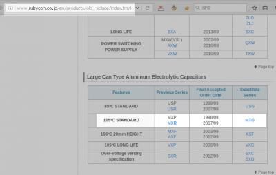
There's a question "How to tell if an electronic component is counterfeit?", and one answer of this question said: QUOTE The best way to avoid this problem is to use reputable suppliers, like Mouser, DigiKey, Element-14, etc. QUOTE(rsseco @ Aug 24 2016, 10:21 PM) My terms are wrong ? Sorry. I think what you know about positive & negative pole of diode is right, it's just typo in your posts. No need to measure them again.But my thoughts are true to say marked side is - pole ? So, normally I always put the Black - pad on this side to have the normal behaviour of the diode, or am I completly wrong ? Are some of my measurments totally wrong then ? QUOTE(rsseco @ Aug 24 2016, 10:21 PM) What should I do next ? Could be I must buy some other capacitors if they are "false" ones ? It's a dilemma, absolutely. I bought from mouser.cn at 2015-05, at that time, mouser.cn need to place order at least ¥150 RMB (China Yuan) if I choose RMB as currency. Now, the minimal total price to place order had increased to ¥175 RMB.EDIT :The fault can be mine too, as I want to buy as cheap as I can... I do it this way, as I doesn't want to spend too much in case my repair will not work. I know it's a risk by having some bad quality product, and it's a dilemma : Low price = bad quality = perhaps repair will not work because of that ; instead of more expensive = best quality = can work better ! If I was sure to be able to repair it by myself, I would buy things of higher quality, of course !  Because usually, I always buy the best things... 
Minimal total price to place order in DigiKey using RMB as currency is ¥500 RMB, which is far more than Mouser, so I choosed Mouser. But DigiKey seems have more choices, for example, Mouser don't have Rubycon capacitors. Because the quantity is too small, so the single price is too high for me, plus the tax and long time shipping/waiting, makes it unacceptable to me, so I may not buy from them again. By the way, I never know Mouser & DigiKey & other professional electronic suppliers until I read this thread. This post has been edited by asenrzhang: Aug 25 2016, 01:31 AM |
|
|
|
|
|
Aug 25 2016, 02:03 AM
Return to original view | Post
#34
|
|
Junior Member
68 posts Joined: Apr 2015 From: China |
Disclaimer: I'm not a professional electronic engineer, not even an amateur, so, take the advice at your own risk. QUOTE(jsmars @ Aug 24 2016, 03:54 AM) Thanks a lot of checking my list! I've replaced the components with your suggestions, since I'm a novice I'd rather go with the safer bet. I've made an updated list here (containing enough for 3 subs), the customer reference is the amount needed for each sub. I'm not sure if I got those resistors from this thread or a friend of mine who looked at the sub, since they aren't that much I'll get them and see if I need to change them or not. All should be covered now right? If your subwoofer symptom is as same as the OP's, the list should covered all now.http://www.digikey.se/short/3htn1f But some other people in this thread also replaced other parts because they encountered different problems. So, if your subwoofer symptom is different, maybe you can post here to see if someone can help identified which parts need to be replaced, then you can place a different order, only buy necessary parts, that could save a lot money. QUOTE(jsmars @ Aug 24 2016, 03:54 AM) Also for the part I missed, is there any part that would have longer than 3000 hours? The other parts I have range between 5000-1000. Would for example this part work? Yes, UPX1V101MPD1TD is a little big larger than UPW1V101MPD,http://www.digikey.se/product-detail/en/ni...16-1-ND/4320150 It's a bit bigger and has a different ripple current and impendence, but the rest is the same. Not sure this moment where on the board they fit and if there is space and if those attribute differences are ok? - lead space is 1.5mm larger - dimension is 2mm larger - height is 10mm larger There're plenty spaces on the 100μF capacitors position, I guess (just guess) this one can fit 3.5mm lead spacing solder pad because bottom of these capacitors does not need to be touch the board, but I'm not sure. You can filter 3.5mm lead spacing in DigiKey search forms. Example filter (100μF, 35V, 3.5mm lead spacing, 5000-10000 hour life): http://www.digikey.se/product-search/en/ca...d=0&pageSize=25 |
|
|
Aug 25 2016, 03:44 AM
Return to original view | Post
#35
|
|
Junior Member
68 posts Joined: Apr 2015 From: China |
Disclaimer: I'm not a professional electronic engineer, not even an amateur, so, take the advice at your own risk. QUOTE(rsseco @ Aug 25 2016, 01:09 AM) OK, I will check this with only Q3 and Q4 soldered. Do I need to try with only one first or can I put the twice together ? Try one by one, or try both of them at same time, are all acceptable.But I may test like this: 1. solder new IRF740 on Q4, test only Q4 first, because it survived in the first time 2. if step 1 passed, then solder new IRF740 on Q3, test Q4 & Q3 simultaneously 3. if step 2 passed, then put heat sink back, mounted Q3 & Q4 to heat sink, test again QUOTE(rsseco @ Aug 25 2016, 01:09 AM) And how will we find what ? Not sure, the unknown reason is what you need to discovered.QUOTE(rsseco @ Aug 25 2016, 01:09 AM) This is not what I already done yet ? Or you mean with some IRF740 in place ? Or in the order you wrote it : first V(G-S) and then V(D-S) ? What you wrote is>> - Q3(S) - Q3(D) : values changing / -/+ values (alternative voltage ?) >> - Q3(S) - Q3(G) : 285mV The testing order of Vgs & Vds is not important. QUOTE(rsseco @ Aug 25 2016, 01:09 AM) No, values fluctuated to fast ! I can try the "A-Hold" mode of the multimeter QUOTE(rsseco @ Aug 25 2016, 01:09 AM) I don't know what to say, the "-" sign appears sometimes... I want to make sure no negative voltage happenedQUOTE(rsseco @ Aug 25 2016, 02:08 AM) OK. And so could be my IRF740 too... and perhaps what I doubt before, could be faulty or fragile too (that's why they broke as easily ?!? ; and could confirm my guess about why 2 IRF740 broke as before, only one was really out of order). It could be IRF740's fault, but I don't suspect it at this time. The IRF740 seller got more positive feedbacks than the capacitors seller.QUOTE(rsseco @ Aug 25 2016, 02:08 AM) But, my fluctuate values without any IRF740 in place could reveal any other problem anyway ? This post has been edited by asenrzhang: Aug 25 2016, 03:14 PM |
|
|
Aug 25 2016, 10:30 PM
Return to original view | Post
#36
|
|
Junior Member
68 posts Joined: Apr 2015 From: China |
Disclaimer: I'm not a professional electronic engineer, not even an amateur, so, take the advice at your own risk. QUOTE(rsseco @ Aug 25 2016, 02:41 PM) In fact, I don't know which was OK at the first time, as I remove twice at a time to check them. I only know one was defective and the other no Sorry, my memory got corrupt.To remember : Before testing, please make sure the components voltage with varying reading value does not encounter a negative reading value. Professional engineer may use oscilloscope to check these signals, that's beyond my knowledge and skills. QUOTE(rsseco @ Aug 24 2016, 04:19 AM) ... If no negative voltage encountered, then test like the following- D1 : 323.6V ! Okay - R2 : 157V Okay - Q3(S) - Q3(D) : values changing / -/+ values (alternative voltage ?) Vds of Q3 should closed to voltage on C59/C69. - Q3(S) - Q3(G) : 285mV - Q4(S) - Q4(D) : values changing / then seems to stop at +147V - Q4(S) - Q4(G) : 287mV - Q1(S) - Q1(D) : 168V - Q1(S) - Q1(G) : values changing - Q2(S) - Q2(D) : 173.5V - Q2(S) - Q2(G) : 0V - C70 : 172V - C69 : 150V - C60 : 172V Voltage on C60 equals voltage C70, as expected. - C59 : Values changing / +/- mV and V Voltage on C59 should equals voltage on C69, like Vc60 = Vc70 0. discharge C59 C60 C69 C70 capacitors first (or unplug power cord and leave it there for one day) 1. solder new IRF740 on Q3, power on to test Q3 2. if step 1 passed, then unsolder Q3, solder it on Q4, power on to test Q4 3. if step 2 passed, then solder new IRF740 on Q3, power on to test Q3 & Q4 simultaneously 4. if step 3 passed, then put heat sink back, mounted Q3 & Q4 to heat sink, power on and test again QUOTE(rsseco @ Aug 25 2016, 02:41 PM) Yes and no ! In fact, I've done it by putting the black pad as you wrote me before. So you wrote "Q3(S) - Q3(G) : 285mV" to log the voltage reading value between G(red) and S(black)?You can see it on this picture (S is written in black, D and G in red) ; I've tested it this way. Okay, G seems to be written in black... but in fact, it's red ! It's okay, I guess it's just a matter of different convention/habit/taste. QUOTE(rsseco @ Aug 25 2016, 02:41 PM) I have an additionnal cap leaving (as I bought 5) ; should I try to replace C59 in order to see if I have stable value ? I'm not really sure if it's capacitors' guilt.Also, if capacitors are faked, there's no point to replace just one of them with another faked one. If capacitors are genuine, you may need to replace both C59 and C69 because of their parallel circuit, which means you don't have enough capacitors. (By the way, genuine Rubycon MXR series only have 3000 hours life.) ==== Just found one interesting article about MOSFET failure pattern and analysis (Chinese), the OP post an image which shows over-voltage and over-current failure. (images only shown to registered user on that forum, so I posted it here) 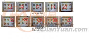
Over-voltage failure (top row) all have a dot/hole in it. Over-current failure (bottom row) usually happened on Source side. So, you may check the cracked one to see which failure pattern it is. The OP use chemical way to disassemble MOSFET, he use something called '氰氟酸'(or 'Hydrofluoric acid' by google translate). ==== You may also want to see this article: Why MOSFETs fail in Solid State TC duty . "Insufficient gate drive, (incomplete turn on)" section attract me, if I understand that section correctly, because you got 0.285V Vgs on Q3 and Q4, that seems like insufficient Vgs, and could lead to a high resistance (Rds) and generate much heat and burned them. This post has been edited by asenrzhang: Aug 28 2016, 01:39 AM |
|
|
Aug 28 2016, 09:43 PM
Return to original view | Post
#37
|
|
Junior Member
68 posts Joined: Apr 2015 From: China |
QUOTE(rsseco @ Aug 28 2016, 08:17 PM) Hi ! Vgs of Q3 & Q4 are around 280V, are you sure? That definitely burn IRF740 -- Vgs should never lower than -20V or higher than +20V, usually it should around +10V.Sorry for the delay, but with these hot summer days, not very easy to do some checks ! By the way, here are the new checks of today ! I re-check Q3 and Q4 completly again. Q3 S->D : 152V, no more fluctuating ! Q3 S->G : 283V Q4 S->D : 148V Q4 S->G : 280V C59 : 157V but decreasing slowly QUOTE(rsseco @ Aug 28 2016, 08:17 PM) I wanted to re-check Q2 and Q1, but on Q2 I ripped the red probe between G and D and what should happen, happened ! Shortcut, electric arc and Q2 explodes ! Be careful when checking components with power on, I burned two tiny components on AMP board when I checking other component with power on, literally burned -- I saw white smoke flow up.For the other 2, I already threw them away... But I don't understand why this time I haven't no more fluctuating values !? ! So next step is to replace Q2, then Q3 ? What's next step? I think you need fix the "Vgs too high" issue first if it's really that high. Vgs in your previous check is only in mV level, I don't know why you got such a high reading value this time, it closed to the reading value of voltage of D1 you last checked! This post has been edited by asenrzhang: Aug 29 2016, 01:33 AM |
|
|
Aug 30 2016, 11:35 AM
Return to original view | Post
#38
|
|
Junior Member
68 posts Joined: Apr 2015 From: China |
Disclaimer: I'm not a professional electronic engineer, not even an amateur, so, take the advice at your own risk. QUOTE(rsseco @ Aug 29 2016, 04:46 AM) Edit : but, if it's mV, you have said it's too low too, so where is the matter now ? My guess is
You can use your first multimeter to test them after unsolder them. For D23 & D24, if your battery in your first multimeter is 9V, they should not be conductive in one direction. You may check D22 & D25 too, just in case. For Q6, I never test a transistor, but you can try switch multimeter to 'hFE' position, then plug the unsoldered transistor to PNP (Q6 is a PNP transistor) to test it ( just make sure each leg is in right position ) This post has been edited by asenrzhang: Aug 30 2016, 11:39 AM |
|
|
Aug 31 2016, 08:44 AM
Return to original view | Post
#39
|
|
Junior Member
68 posts Joined: Apr 2015 From: China |
QUOTE(jsmars @ Aug 31 2016, 07:04 AM) Hey, I'm working on soldering on my first set now that my components have arrived. Looking over my list I haven't actually found the location for two of the components. The other 47μF is closed to the 0.1μF one, it's wrapped by black stuff, see the photo below.* I've only found one of the 47UF 25V, the one next to the 35UF 100V, where is the other one? * The only 0.1UF 50V I can find is a cylindracal one (similar to the others), but the one I've got on my list is a small yellow ceramic capacitor (this one: http://www.digikey.se/scripts/DkSearch/dks...81768803203599). Is this the one I should replace? Is that ok that they are so different? Thanks for any help! And yes, @lex use a ceramic capacitor like yours to replace the 0.1μF one(C63) instead of original electrolytic capacitor. This post has been edited by asenrzhang: Aug 31 2016, 08:48 AM Attached thumbnail(s) 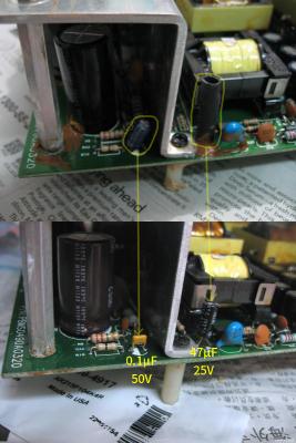
|
|
|
Aug 31 2016, 10:20 AM
Return to original view | Post
#40
|
|
Junior Member
68 posts Joined: Apr 2015 From: China |
QUOTE(jsmars @ Aug 31 2016, 09:30 AM) Interesting! I actually looked under that rubber tubing and found a Yageo 47UF 63V. Could it possibly be that this one isn't an original? This set was actually in for repairs a number of years ago, but I only noticed one other fix that they actually did, but could I be sure that this one is also part of that fix then? Should I leave it be or put my 47UF 25v there? See picture. Also, is this tubing important to get back? The original one is 25V rating, so it had been replaced in previous repair.You may leave it there, because I saw someone in another forum (Chinese) said: This one is related to the power reset issue (press standby/power button, power is on but go off immediately, then go back in standby state again), and should be replaced with a higher voltage rating capacitor. (I didn't verified if it's true or not, I left this issue there, because I can still power on my subwoofer) Or you can replace it, if power reset issue occurs, then put it back. The black tube, I don't think you can put it back again, it's some kind of shrinking tube via heat. @lex and others didn't put it back, me neither. QUOTE(jsmars @ Aug 31 2016, 09:30 AM) Also one more question: On my list I had 3 1000UF 100V, but looking around I can only find two of these, one on each amp. Is it just 2 or am I missing something? QUOTE(jsmars @ Aug 24 2016, 01:04 AM) ... You only need two 1000μF 100V. I guess you bought an extra one as you said before.I will order 2x the amounts ofcourse since I have two sets and probably a few extra of most of them just in case ... This post has been edited by asenrzhang: Sep 9 2016, 09:47 AM |
| Change to: |  0.0514sec 0.0514sec
 0.33 0.33
 7 queries 7 queries
 GZIP Disabled GZIP Disabled
Time is now: 7th December 2025 - 12:56 PM |
 Quote
Quote