 Disclaimer: I'm not a professional electronic engineer, not even an amateur, so, take the advice at your own risk.
QUOTE(rsseco @ Jan 6 2017, 12:37 AM)
Hi !
I'm back and happy new year !
Happy new year!
QUOTE(rsseco @ Jan 6 2017, 12:37 AM)
So today, I decided to re-assemble my S750 again after a sooo long time !
I soldered back all the diods, PNP, changed the 3x IRF740, and let's go to the testing :
- No heatshrink mounted, powered on with CN4 and CN5 unplugged : OK
- No heatshrink mounted, powered on with CN5 plugged and CN4 unplugged : OK
- Same thing, but I pugged CN4 too (twice are now plugged) : and here something went wrong (heard a "pffff" noise and fuse blown)
Did you replaced all the electrolytic capacitors on PSU board?
Since we are beginners, no enough experience and equipment to check, I would like to follow @lex's guide to replace all electrolytic capacitors on PSU board first, then do the test.
QUOTE(rsseco @ Jan 6 2017, 12:37 AM)
So it could be one of the amplifier board which are defective ? I know I didin't take off the glue on these boards, perhaps that could be the wrong thing ?
I take a short look to find what could have blown (the "pfff" sound) but didn't find something yet. Perhaps another capacitor ?!?
Any ideas ?
Not sure it's AMP board's fault or not. The glues for biggest capacitor on AMP board are 'white' glues, I think it don't need to be removed.
I don't know what the 'pfff' sound came from, maybe it came from the blown fuse itself.
I would like to do the following before testing
- Replace all electrolytic capacitors on PSU board
- Check CN4 CN5 voltage before testing
And when testing, add one test case: plug CN4, unplug CN5, then test.
-------------
By the way, I bought a failed subwoofer, and try to repair it for fun.
The previous owner said it does not power at all, no LED light, nothing.
After fixing, LED on back plate and control pods are back, press the "STANDBY/POWER" button, the "MASTER" led turns on, but it doesn't actually power up: no click sound came out from the relay.
I measured the output voltage of CN6, all the voltage reading values are about half of value it should be.
I suspect it's the fault of T3 (transformer 3), but I'm not sure (even I'm sure, I can't found a proper replacement now), and I'm stuck here.
Hope somebody can help me to find out the source issue.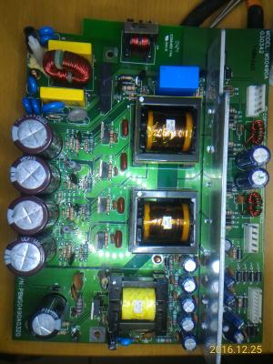

All the electrolytic capacitors on PSU board had been replaced (but the 35V/100μF were replaced with 35V/220μF, because I forgot to bought them...)
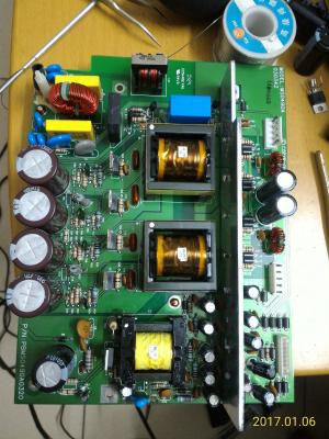 Update 1 (2017-01-07 02:50)
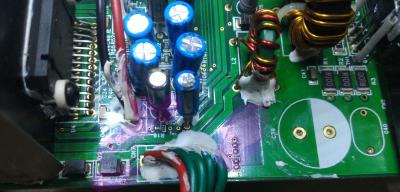
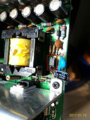
I just desoldered the opto coupler (U2), clean it, check it (
seems fine, but I'm not sure), and I soldered it back, luckily, I can turn on the main power now.
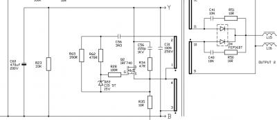
There's explosion sign under C62 which is near to the opto coupler, I guess the explosion had affected the feedback circuit somehow.
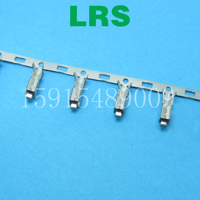
Update 2 (2017-01-08 00:50)The subwoofer does not produce sounds even the main power is on. After careful check, I found that the +24V and -24V voltage are still low (around +17V and -17V), and 4 terminals of VH connector of power lines from/ AMP boards are broken (the tongue is broken/missing).
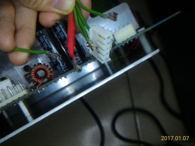
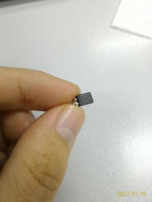
So I bought some opto couplers and terminal components, waiting for the arrival...
 Update 3 (2017-01-10 20:30)
Good news, after I replaced the optocoupler (U2), the subwoofer can produce sounds now !
In update 1, I thought it's okay, but it's not!
The resistance between 3 and 4 pin/leg is about 1040 Ohm, in both direction, without powered on.
-------------
Just for fun:
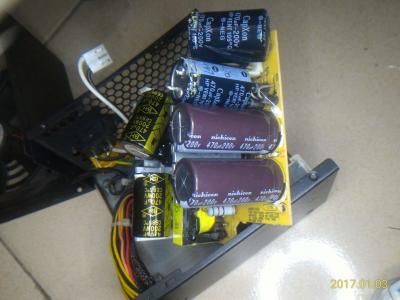
My PSU of desktop computer failed last week.
Symptom: Keeps rebooting without BIOS booted.
I disassembled the PSU, found two capacitors in it, and their rating are the same as S750's: 200V/470μF/22mmx35mm.
I measured the capacitance of them, only 320μF (68%) left. So I replaced them with two capacitors which were desoldered from S750, guess what, IT WORKS!
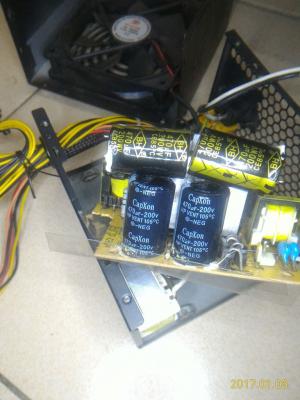
But for long term consideration, I bought two new Nichicon PW series capacitors and replaced those two CapXon capacitors.
 This post has been edited by asenrzhang: Jan 10 2017, 09:47 PM

 Sep 4 2016, 04:18 PM
 Quote
Quote


 .
. ", said by


 if my s750 will get back to live again i will get all of the AMP and IO and Power board out of the sub-woofer and i will make a custom box for AMP,etc and just a small wire get into the sub-woofer for the sub-woofer sound , and i will keep the amp and other board cool with a FAN or something else maybe i put it in the freezer
  0.0398sec
 0.37
0.37
 7 queries
 GZIP Disabled