QUOTE(Audison @ Mar 19 2014, 02:58 AM)
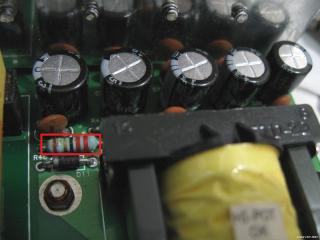
Hi Lex and others posting in this thread! I just wanted to say Thank you! to all of you for making information about this sound system available as it helped tremendously when fixing my set of S750. I would probably never dared to open it, if it was not for this thread that give me all information i needed about the components and other stuff. I am not an expert in this field so apologies if i am going to be asking very basic stuff that anyone should know. I already replaced all the capacitors that was recommended in this thread but i need to replace one resistor that has died but i can't really read the colors down and all the measuring does give me not really clear idea of what resistance he is. i am going to attach an image or the picture that was posted above with my resistor marked. Thanks again for all your help.

» Click to show Spoiler - click again to hide... «
Its 22 Ohms. That resistor is part of a RC snubber network around the recitfiers. I would recommend Google "resistor color code" to find references to resistor values, as well as online resistor color code calculators.

QUOTE(Mikoman @ May 8 2014, 09:00 PM)
Hi Lex, all,
Thanks for amazing tutorial. I fixed my s750. This is awesome.
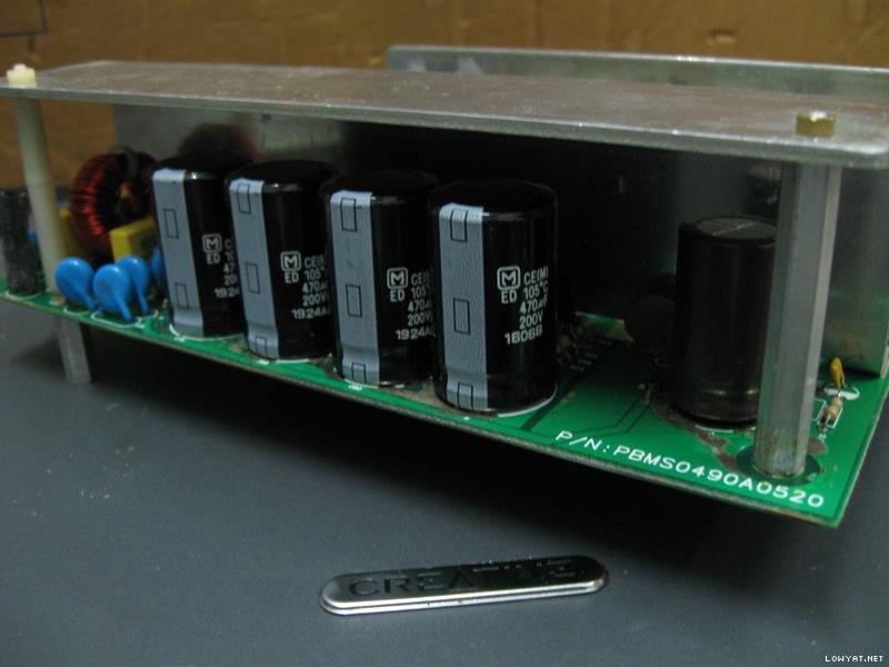
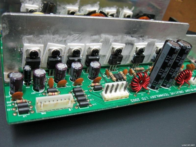
I have replaced all capacitors with panasonic ones. I wonder if there is something wrong or it's normal behavior but the "L" type cooler on the power board (the one near big capacitors) is extremely hot even when i listen the music on low volume. So i added another massive cooler (marked with red arrow) to it and seems a lot better now but still hot. I quess that's why they used 105 degrees capacitors

» Click to show Spoiler - click again to hide... «
Well, a fan mod would do better to cool down the components though would be more work than just attaching an extra heatsink. I've had another one repaired not long ago. Not as pretty as the first few shown here (due to very stubborn degraded glue)..

» Click to show Spoiler - click again to hide... «
QUOTE(Mikoman @ May 8 2014, 09:00 PM)
I had the same issue like Galeak with immediate power of after a power on so i ordered those DB3 for replacement. So hopefully it will help.
Anyways after the replacement of all capacitors the green light was ok but the red light on the remote was death. I searched a little bit and found this
THE PROBLEM WITH THE ?CONTROL POD IF NO WORK, ONLY OPEN USING SCREWDRIVERS
LOOK ONE MICROCHIP ?M34502E4FP?, MAIBE CPU IT IS IN RESET STATE. THE ONLY THING YOU HAVE TO DO IS GET A SOURCE WITH 5 VOLTS DC AND PUT THE NEGATIVE LINE IN THE PIN 2 COUNTING SINCE MARK AS NUMBER AND THE POSITIVE LINE (+) ?IN THE PIN 6 IT IS THE RESET, IF NO ON RED LIGHTS IN THE CONTROL POD PUT THE POSITIVE LINE IN THE 7 PIN THIS PIN IS P2Ain THATS SUPPLY 5V DC TO DE STAND BY BUTTON MANUALLY AND RESET DE POD.
NOW RETIRE THE SOURCE OF 5V OF THE PINS AND THE POD IS WORKING NORMALLY. BE CAREFULL PUTING LINES (+) AND (-) ON THE PINS OF THE MICRO THAT NO JUMP WITH ANOTHER PINS.
HOPE THAT SOLVE THE PROBLEMS.
And this solved my problem (i did both steps with pin 6 and 7). Hope it will help to someone as well.
Cheers
Have not yet encountered such problematic control pods, though the usual problems I've encountered is the glitchy standby button (which causes quick on-then-off sometimes) due to worn microswitch inside. The other one, was the stuck volume button caused by misaligned plastic contact internally (can be fixed easily). As for the problem described above, thanks, will look into it when/if I've encountered one of these...


 Feb 25 2014, 05:32 AM


 Quote
Quote


 0.0336sec
 0.35
0.35
 6 queries
 GZIP Disabled