QUOTE(limhongwoon @ Dec 25 2010, 07:42 PM)
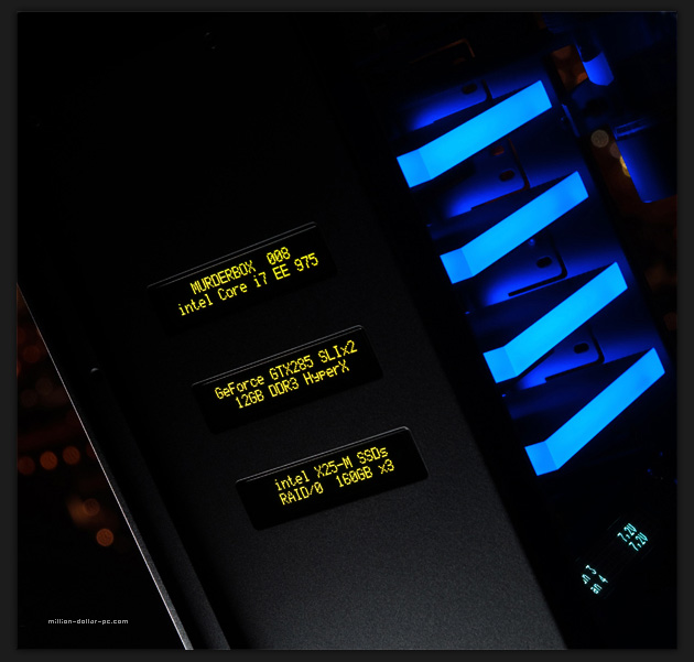
The MurderBox is using what type of LCD ? 16x2 Character LCD or 20X4 Character LCD ? One USB can connect how many LCD ?
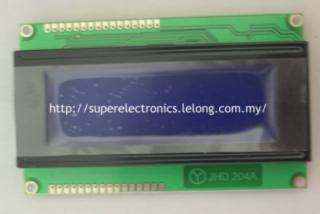
If you count the longest text display on the LCD, it is around 20 characters... but have 2 lines only... 20 x 2 type or longer...
I think he is using a uncommon LCD module ...
From the URL, I saw that the fellow hv another LCD inside the case to display all the temp and such and the three LCD at the front are static LCD only..
So my guess is that those 3 LCD are static display only and the text does not change ... no need to use USB, just wire up a microcontroller to the LCD, send the codes/programming to the microcontroller with the text
line 1 " Super Duper Mod 002"
line 2 "Intel Core i 7 xx 888"
and power it up from the +5V molex with some resistors.. totally not connected to the PC at all...
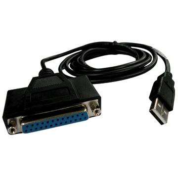
When you need to change the text, just plug in the USB/Serial TTL and re-programme it... I've an article on my blog/facebook page on it..
Each Arduino microcontroller could drive like 1 LCD bcos each LCD would take up 3 control pins and 4 data pins...
If you needed 3 Arduino for this purpose with LCD module, I can make them for you cheaply if you are intertested...
Added on December 26, 2010, 10:23 amQUOTE(limhongwoon @ Dec 25 2010, 07:42 PM)
The MurderBox is using what type of LCD ? 16x2 Character LCD or 20X4 Character LCD ? One USB can connect how many LCD ?
If you count the longest text display on the LCD, it is around 20 characters... but have 2 lines only... 20 x 2 type or longer...
I think he is using a uncommon LCD module ...
From the URL, I saw that the fellow hv another LCD inside the case to display all the temp and such and the three LCD at the front are static LCD only..
So my guess is that those 3 LCD are static display only and the text does not change ... no need to use USB, just wire up a microcontroller to the LCD, send the codes/programming to the microcontroller with the text
line 1 " Super Duper Mod 002"
line 2 "Intel Core i 7 xx 888"
and power it up from the +5V molex with some resistors.. totally not connected to the PC at all...
When you need to change the text, just plug in the USB/Serial TTL and re-programme it... I've an article on my blog/facebook page on it..
Each Arduino microcontroller could drive like 1 LCD bcos each LCD would take up 3 control pins and 4 data pins...
If you needed 3 Arduino for this purpose with LCD module, I can make them for you cheaply if you are intertested...
This post has been edited by stan001: Dec 26 2010, 10:23 AM 

 Nov 22 2010, 11:50 PM


 Quote
Quote


 thanks!


 0.0267sec
 0.58
0.58
 6 queries
 GZIP Disabled