Welcome Guest ( Log In | Register )

5 Pages « < 2 3 4 5 >Bottom

Outline · [ Standard ] · Linear+

 Nice Mod add-on : LCD Module on your desktop, Character 4x20 LCD Module

views
     
TSstan001
post Jan 7 2011, 12:00 PM

On my way
****
Senior Member
623 posts

Joined: Jan 2003
From: Kuala Lumpur


QUOTE(jeopardise @ Jan 7 2011, 11:42 AM)
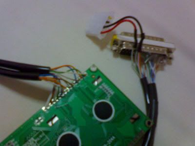
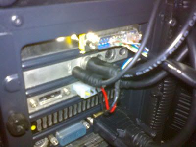
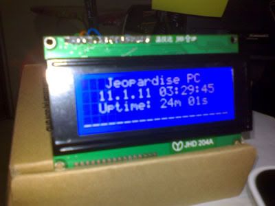
At 5 volts from molex (YES I connects to the red line)
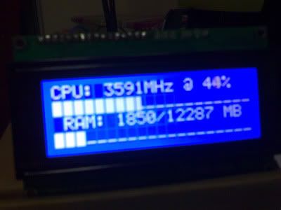
Line 1 and 3 appears darker than 2 and 4. Izzit normal?
*
No, it is NOT normal.. but you mention if voltage is 6V, then it shows all even brightness...

If power is sufficient, then it should NOT show uneven lines... use the trimpot connected to pin 3 to adjust until all show the darkness evenly..

You might need current limiting resistor on pin 15 & 16 bcos current from the molex is quite high... (it might work but it would reduce the life of the LCD )


jeopardise
post Jan 7 2011, 05:05 PM

tidak memberi seketul tahi!
******
Senior Member
1,767 posts

Joined: Jan 2003
From: Bandar Seri Putra


I will try to find a trimpot to control the contrast. I usually salvage components from damaged electronic parts tongue.gif

May the FORCE be with me!

This post has been edited by jeopardise: Jan 8 2011, 01:32 PM
jeopardise
post Jan 8 2011, 01:33 PM

tidak memberi seketul tahi!
******
Senior Member
1,767 posts

Joined: Jan 2003
From: Bandar Seri Putra


]Hi stanley,

Could you show me a simple wiring diagram to control the contrast? tq

It seems my LCD module issue has been discussed here. See what can I do hmm.gif

This post has been edited by jeopardise: Jan 8 2011, 01:43 PM
TSstan001
post Jan 8 2011, 02:21 PM

On my way
****
Senior Member
623 posts

Joined: Jan 2003
From: Kuala Lumpur


Pic is here :-
Like this : http://arduino-for-beginners.blogspot.com/...les-part-1.html

Potentiometer or trimpot have 3 pins.. ( voltage divider )

Connect pin 1 to 5V
Connect pin 2 to pin 3 of LCD
Connect pin 3 to ground

Adjust the pot until you get all BLACK bar...


jeopardise
post Jan 8 2011, 02:37 PM

tidak memberi seketul tahi!
******
Senior Member
1,767 posts

Joined: Jan 2003
From: Bandar Seri Putra


in my case, the LCD has blue backlight .

So BLACK bar means the bar darker than the backlight OR brighter than backlight?

Attached Image

should appear white right?


Added on January 8, 2011, 3:03 pmI googled around and found this:

QUOTE
Quote:
I then tried using the LCD4Bit library and example sketch, but all i get are 2 lines of black squares on the 1st & 3rd line, and the compiler didn't show any problem before upload.

When you get the two lines of black squares it means that you have the power applied and the contrast set properly but the LCD controller has not been initialized properly. 

Many of the libraries that are available do not follow the datasheet recommendations to use software initialization or they do not implement that initialization properly. 

I suggest you try the latest official LiquidCrystal library (Arduino v0017) and try the accompanying example programs.  This library follows the datasheet more closely than all the others and should work for you.

Don


From: http://www.arduino.cc/cgi-bin/yabb2/YaBB.p...=1251279124/6#6

QUOTE
When you say it goes to full bars, do you mean ?

I had an issues where i got the lines of black squared on lines 1 & 3 of the LCD which meant it wasn't initializing the screen. which i suspect is the same for you.

Make sure you have the lcd initialized with the following code, and just make sure the pins defined match the input/output pins you are using ?

Quote:
// initialize the library with the numbers of the interface pins
LiquidCrystal lcd(12, 11, 5, 4, 3, 2);


It seems this LCD is a bit different. Looks like I have to program the LCD to initialize it properly.

I think I wanna buy 2x20 module that u're using perhaps can work out of the box. Not so ready to do some programming though cry.gif

Another issue here : http://translate.google.com/translate?js=n...php%3Ft%3D28415

Looks like it's not the contrast problem. I have tried to arjust with the pot, no change. rclxub.gif

This post has been edited by jeopardise: Jan 8 2011, 03:12 PM
TSstan001
post Jan 8 2011, 11:57 PM

On my way
****
Senior Member
623 posts

Joined: Jan 2003
From: Kuala Lumpur


QUOTE(jeopardise @ Jan 8 2011, 02:37 PM)
in my case, the LCD has blue backlight .

So BLACK bar means the bar darker than the backlight OR brighter than backlight?

Attached Image

should appear white right?
Yes, it should be WHITE for yr case... smile.gif

I've a 4x20 LCD Black on Green, YES, it should be line 1 & 3 lit up full bar ...

I use a voltmeter to measure pin 3, the voltage is very small, in mV, so if you want full bar, just ground it for 0V.. and skip the trimpot... like the website you mentioned.

All these character based LCD are using the HD44780 protocol... can be different sizes, 16x2 20x4 or 40x2... all the same way of driving it..

Pin 15 & 16 are for the backlight, connect 15 to Ground and 16 to 5V..

*** Some of these LCD, the viewing angle is small, it will look full brightness (or darkness) at direct angle and looks dimmer at different angle..


jeopardise
post Jan 9 2011, 10:30 AM

tidak memberi seketul tahi!
******
Senior Member
1,767 posts

Joined: Jan 2003
From: Bandar Seri Putra


QUOTE(stan001 @ Jan 8 2011, 11:57 PM)
Yes, it should be WHITE for yr case... smile.gif

Pin 15 & 16 are for the backlight, connect 15 to Ground and 16 to 5V..
pin 15 should be power +5v while pin 16 should be ground right?
TSstan001
post Jan 9 2011, 10:57 AM

On my way
****
Senior Member
623 posts

Joined: Jan 2003
From: Kuala Lumpur


QUOTE(jeopardise @ Jan 9 2011, 10:30 AM)
pin 15 should be power +5v while pin 16 should be ground right?
*
Usually...on the datasheet, they are called Cathode(K) & Anode(A) (similar to a LED) but I've one LCD with the K & A reversed.

If one way did not work, just swap it around..

So did you managed to get the LCD working for LCDSmartie software yet ?

My case when I first constructed the Parallel port version, I had some grounding issues, so I need to trace all the cables...

Post some pics of your circuits with the LCD


jeopardise
post Jan 9 2011, 12:01 PM

tidak memberi seketul tahi!
******
Senior Member
1,767 posts

Joined: Jan 2003
From: Bandar Seri Putra


All right, I will post some pics later.

To make the LPT1 port, I might use VMware with Windows XP as client. Porting the LPT1 to host LPT1 might work or for the last resort I might install Windows XP 32bit natively. This is because port95nt incompatible with Windows 7 x64. If it work with XP just to confirm the LCD working, I'll try other dlls to make it work in 64bit.

My soldering iron just died while I am trying to rebuild my wiring vmad.gif . Until I get a new one.

This post has been edited by jeopardise: Jan 11 2011, 09:43 AM
jeopardise
post Jan 11 2011, 09:44 AM

tidak memberi seketul tahi!
******
Senior Member
1,767 posts

Joined: Jan 2003
From: Bandar Seri Putra


Thanks stan001 for your helps.

At last it worked! rclxms.gif

1. Using VMware with LPT1 emulation with Windows XP client: The method to confirm LCD module and wiring is correct with port95nt (only works for 32bit windows) drivers.

Seems like the parallel black bar will automatically gone when the parallel port initialized by LCD smartie.


2. Using inpout32.dll (supporting x64 OS) now works (after some try and error)

The correct method is to copy Inpout32.dll for Windows 98/2000/NT/XP
into LCD Smartie root folder (overwrite the existing inpout32.dll) and renaming another copy of it to DLPortIO.DLL in the same folder.

QUOTE
Notes:
From Version 1.0.0.7, I have added, simple compatibility with DLPortIO that should allow LCDSmartie to use this DLL as a drop in replacement for DLPortIO in x64 windows. To do this, download just the binaries only package (below) then take the 32bit DLL (in the \Win32 folder), rename it to DLPortIO.DLL and copy it to your LCDSmartie folder. Read the DLPortIO.TXT file included in the ZIP for more information.

I have had confirmation that 1.0.0.7 works with LCDSmartie in Windows 2003 x64 using the above method.


You may get a "side by side" error when running Installdriver.exe on Vista (especially 64bit Vista). If you do, you can try downloading the latest Microsoft C++  runtimes (2005 SP1). For the 32bit version, go here. For the 64bit version, go here.
Some photos brows.gif

user posted imageuser posted image
My wiring using CAT5 cables from backyard. 5V power taken from molex +5v power from e-SATA power bracket.

user posted imageuser posted image


I think I will go for USB version soon. At the moment I am waiting for an extra 2x16 LCD module already otw to my address. Perhaps I wanna make this one to display static text. I also will do a housing for the LCD module to attach it to my PC. thumbup.gif thumbup.gif

This post has been edited by jeopardise: Jan 13 2011, 05:43 PM
TSstan001
post Jan 11 2011, 12:03 PM

On my way
****
Senior Member
623 posts

Joined: Jan 2003
From: Kuala Lumpur


QUOTE(jeopardise @ Jan 11 2011, 09:44 AM)
Thanks stan001 for your helps.

At last it worked!  rclxms.gif
rclxms.gif rclxms.gif

Yes, Vmware surely works cos I did mine on WinXP on a Mac via Vmware Fusion...

For acrylic case look for lun1986 ..

Sometimes, if we manage to fixed the issue , you will learn more about how it works!!! Or else we just blindly follow the HOWTO without knowing what is going on..

I m researching to do "static LCD" with the lowest possible cost using DIY Arduino microcontroller + LCD only.. stay tuned...


jeopardise
post Jan 11 2011, 01:20 PM

tidak memberi seketul tahi!
******
Senior Member
1,767 posts

Joined: Jan 2003
From: Bandar Seri Putra


Hi stan001 smile.gif,

U r right! Once it works, it seems this is so easy.

I hope I could find the USB FTDI chip like yours. It seems it also supported on MacOX and have device driver for it. Until I got budget for it, I'll personally ask for you recommendations later.

Arduino UNO also not bad. I'll definitely need one as it'll eliminate the use of PCI slot for LPT, less wiring troubles and also less hassle to enable the device in 64-bit.

In my case, I can't make it work by using "LPT1" parameter in LCDSmartie.exe. It is recognised by HD44780.dll by using address "$E880"
jeopardise
post Jan 20 2011, 11:27 AM

tidak memberi seketul tahi!
******
Senior Member
1,767 posts

Joined: Jan 2003
From: Bandar Seri Putra


I've made a proper housing for the LCD module and add 2 analogue VU meter from Coolermaster Musketeer. rclxms.gif Internally, there are two completely different circuits actually.

user posted image

With perf, fanspeed, aida64, winamp and keyboard shortcut plugins for LCD smartie, it totally rawks rclxm9.gif
dakwan5555
post Feb 23 2011, 06:07 AM

Getting Started
**
Junior Member
85 posts

Joined: Jul 2009


I'm interested in doing this. Do you do supply of the set? How much is the damage? smile.gif
TSstan001
post Feb 23 2011, 11:36 AM

On my way
****
Senior Member
623 posts

Joined: Jan 2003
From: Kuala Lumpur


QUOTE(dakwan5555 @ Feb 23 2011, 06:07 AM)
I'm interested in doing this. Do you do supply of the set? How much is the damage? smile.gif
*
I'm just posting a DIY solution to add LCD to yr desktop, not really selling it cos it is more fun to do it DIY style and you can customise it anyway you like it..

I think I've posted the parts and estimated cost in the beginning few posts...

You would need some basic soldering skills and can blindly follow the instructions without knowing what is going on..


dakwan5555
post Feb 23 2011, 12:37 PM

Getting Started
**
Junior Member
85 posts

Joined: Jul 2009


QUOTE(stan001 @ Feb 23 2011, 11:36 AM)
I'm just posting a DIY solution to add LCD to yr desktop, not really selling it cos it is more fun to do it DIY style and you can customise it anyway you like it..

I think I've posted the parts and estimated cost in the beginning few posts...

You would need some basic soldering skills and can blindly follow the instructions without knowing what is going on..
*
Sorry bro, here in Perak we have no kedai/dealer selling those electronic components in kit form... I just want it in the kit form.
dchew
post Feb 24 2011, 12:43 AM

Casual
***
Junior Member
325 posts

Joined: Jan 2008
From: somewhere i belong


nice guide, sarawak here dont have it also.
jeopardise
post Mar 8 2011, 10:00 PM

tidak memberi seketul tahi!
******
Senior Member
1,767 posts

Joined: Jan 2003
From: Bandar Seri Putra


try getting one from lelong.com.my.

I directly call/sms the seller for quick response biggrin.gif

I still have one 16x2 module haven't utilized. Perhaps i'll connect it to the office PC. I haven't tried the USB kits.

This post has been edited by jeopardise: Mar 8 2011, 10:03 PM
amir93
post Mar 9 2011, 02:39 PM

Getting Started
**
Junior Member
234 posts

Joined: Nov 2010
From: Alor Setar/Ayer Keroh


im interested but have no idea what is going on. any help sifu how to start the project ?
jeopardise
post Mar 17 2011, 12:03 AM

tidak memberi seketul tahi!
******
Senior Member
1,767 posts

Joined: Jan 2003
From: Bandar Seri Putra


QUOTE(amir93 @ Mar 9 2011, 02:39 PM)
im interested but have no idea what is going on. any help sifu how to start the project ?
*
what do you have got so far?

5 Pages « < 2 3 4 5 >Top
 

Change to:
| Lo-Fi Version
0.0243sec    0.38    6 queries    GZIP Disabled
Time is now: 19th February 2025 - 12:22 AM