Welcome Guest ( Log In | Register )

Outline · [ Standard ] · Linear+

 Nice Mod add-on : LCD Module on your desktop, Character 4x20 LCD Module

views
     
TSstan001
post Oct 2 2010, 01:33 AM, updated 14y ago

On my way
****
Senior Member
623 posts

Joined: Jan 2003
From: Kuala Lumpur


I was always curious on how HTPC makers put in Character LCD Module on the front of the chassis..

I did some searches and found this cool software called "LCD Smartie" and there are lots of cool videos on this topic in Youtube..

http://www.youtube.com/watch?v=zkW8VzkgtlI

I find it pretty cool to output the winamp spectrum analyzer to the LCD module and you can also output stuff like upload/download speed, CPU, memory, hard disk space and other PC stats to the LCD...

This is very good when playing games or watching movies so that you know how much the CPU & memory is used up while in the game/movie...

Best on Parallel port ( but not all modern desktop have it ) or go the USB method using either Arduino microcontroller or USB LCD ( still doing research on this one, if you know how to , pls share... )


Initially after getting an Arduino microcontroller, I did this setup using a USB/Serial connection to the LCD Module..
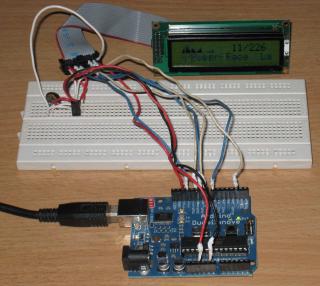
Attached Image

Later I was being more adventurous and got 2 version of the LCD Module, 2x16 and 4 x 20 ( line x columns )...and made this below ..
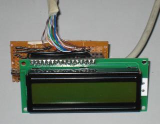
Attached Image

Board with LCD Module removed...

Attached Image

There are 10 cables connected to the parallel port and I am using UTP cables ( 4 pairs plus another 1 pairs, total 10 wires ). The other cable is the USB cable with one end cut off for the 5V power supply taken from USB hub or directly from the USB port...

Later upgraded to a 4x20 LCD Module...

Attached Image

and put everything into a black cardboard box on top of my desktop just below the LCD monitor...
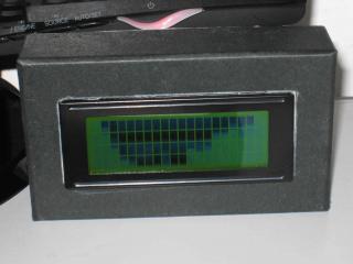
Attached Image


Parallel LCD wiring, credits goto the webpage below.. I just follow his wiring and did some modifications..
http://www.icehw.net/article.php?id=104

Feel free to ask any questions ...


Parts used ( all obtain locally in Jalan Pasar ) :-

2x16 or 4x20 LCD modules purchased from Jalan Pasar
1 x trimpot 10K resistors to control the contrast
Cat 5 UTP cables ( needed 10 wires - as long as you needed to connect from the parallel port to the desktop )
1 x USB cables with one end cut off for the 5V power
1 perf board
1 x 16 pin male header soldered to the LCD Module
1 x 16 pin female headrr on the perf board


A LYN forumer selling the 20x4 USB LCD product. The WTS link is here

This post has been edited by stan001: Feb 24 2012, 02:01 PM
TSstan001
post Oct 2 2010, 01:29 PM

On my way
****
Senior Member
623 posts

Joined: Jan 2003
From: Kuala Lumpur


The cost of everything is less than RM50 ... the LCD module is around RM40..

The software is LCD Smartie

The rest of the stuff like perf board, trimpot, perf board, pins and headers are all around RM1-2 only.. wires ( 10 pcs according to your own length ) ...

Forgot 1 parts : DB25 male + cover

http://www.bizchip-components.com/shop/ind...?productID=7528

Can solder directly from the DB25 male port ( parallel port ) to the LCD module and bypass the additional parts like perf board and header pins.. I made mine more portable as I can switch between 2x16 and 4x20 module..

There are a few online sellers if u r not located at Klang Valley..search for "LCD Module" on lelong.com.my

There are backlight on pin 15 & 16 but when I took the pic with flash, cannot "see" the backlight in the picture..


TSstan001
post Oct 2 2010, 04:27 PM

On my way
****
Senior Member
623 posts

Joined: Jan 2003
From: Kuala Lumpur


Yes, RM40 for the 4x20 , the 2x16 is cheaper around RM20 only but less lines so less stuff can be displayed...

No, I did not use the parallel cables cos I have a lot of long Cat5 UTP cables around, I just strip off the rubber cover and took 10 wires...

The USB version ( for most ppl without Parallel port ) instruction is below if you can find the FTDI USB/Serial module locally...

http://forums.lcdsmartie.org/viewtopic.php?f=11&t=1540


TSstan001
post Oct 3 2010, 11:17 PM

On my way
****
Senior Member
623 posts

Joined: Jan 2003
From: Kuala Lumpur


I'm not sure what you mean by deMUX... the PIC controller should do the following functions like an Arduino :-

- Act as Serial USB to the computer
- Once the drivers are installed for the USB Serial adapter, LCD Smartie software should be able to talk to the Serial port directly using MatrixOrbital plugins ( Matrix Orbital makes serial LCDs )...

From their forum, they are using FTDI chipsets/module to wireup the Serial/USB LCD... the wiring looks pretty simply...

http://forums.lcdsmartie.org/viewtopic.php?f=11&t=1540

This module can be found locally (FTDI BASIC BREAKOUT 3.3/5V) but I have not tested if it is supported by LCD Smartie software or plugins..

http://www.myduino.com/index.php?route=pro...5&product_id=91


Added on October 8, 2010, 11:10 amUpdates :-

You can have LCD shield on an Arduino powered by a USB with 5 buttons for those that do not know how to do soldering or DIY stuff...

http://www.nuelectronics.com/estore/index....ject_lcdsmartie

or

http://www.instructables.com/id/Arduino-wi...artie-over-USB/


Found that there is current a bulk orders for the Arduino board and the LCD Shield..

http://forum.lowyat.net/index.php?showtopi...&#entry36288604

This post has been edited by stan001: Oct 8 2010, 11:12 AM
TSstan001
post Oct 12 2010, 10:58 AM

On my way
****
Senior Member
623 posts

Joined: Jan 2003
From: Kuala Lumpur


YES it can control the LCD Smartie s/w according to the URL and the codes supplied ( since it is open source ), they did modified the LCD library to support the 5 buttons located on the LCD Shield. ( Arduino add-ons )

QUOTE
http://www.nuelectronics.com/estore/index....ject_lcdsmartie

3.2 Interrupt driven Keypad scanning routine
An interrupt driven Keypad scanning routine is used to capture key press from the Joystick keypad inputs. Timer2 is used to generate interrupt at 4ms interval. The interrupt routine records the key press by reading AD0 value and comparing with keypad value stored in an array. A debounce mechnism is also implemented. The interrupt routine then transfer the key press to LCD Smartie software running on the PC. The key press is useful for controlling PC applications, such as Winamp Player.
TSstan001
post Oct 28 2010, 05:00 PM

On my way
****
Senior Member
623 posts

Joined: Jan 2003
From: Kuala Lumpur


Updates..

I've finally made a USB version of the LCD Module for LCD Smartie in bit-bang mode...

Attached Image
TSstan001
post Oct 29 2010, 09:45 AM

On my way
****
Senior Member
623 posts

Joined: Jan 2003
From: Kuala Lumpur


Updated photos with nicer wiring...

LCD module is 4x20

Attached Image

Note - Backlight is on but the flash have covered the light..


TSstan001
post Oct 29 2010, 10:48 AM

On my way
****
Senior Member
623 posts

Joined: Jan 2003
From: Kuala Lumpur


Most parts except for the FTDI board...

Can you make something like this with Arcylic like the Youtube below...

Dunno what materials they use ...
http://www.youtube.com/watch?v=pJ9y3uAZlYo


TSstan001
post Oct 30 2010, 06:07 PM

On my way
****
Senior Member
623 posts

Joined: Jan 2003
From: Kuala Lumpur


QUOTE(lun1986 @ Oct 29 2010, 01:49 PM)
can, the material name "Arcylic" biggrin.gif
*
Yes, i know.. how to cut it according to the size I needed ?

Never deal with arcylic before leh..

I hv both B&D elec drill and B&D RTX "dremel" ... can I use these tools to cut it ??

Thanks
TSstan001
post Oct 30 2010, 09:50 PM

On my way
****
Senior Member
623 posts

Joined: Jan 2003
From: Kuala Lumpur


QUOTE(ryudox @ Oct 30 2010, 08:05 PM)
have u tried using old phone screen such as nokia 3310? i have a lot but dont know how to use it...lolz
*
Did some searches and found the following for you :-

Arduino codes and library :-
http://www.arduino.cc/playground/Code/PCD8544


Nokia 3310 display uses the below driver :-
http://www.myplace.nu/mp3/files/pcd8544.pdf

Schematics to connect an ATMEGA to the nokia display module..
http://www.flickr.com/photos/fallens/120708373/


TSstan001
post Nov 1 2010, 04:31 PM

On my way
****
Senior Member
623 posts

Joined: Jan 2003
From: Kuala Lumpur


QUOTE(lun1986 @ Oct 30 2010, 10:23 PM)
is tis all code for free source user/developer??
*
All the Arduino codes are open source and freely available , you can modify it anyway you like...


TSstan001
post Nov 17 2010, 12:30 AM

On my way
****
Senior Member
623 posts

Joined: Jan 2003
From: Kuala Lumpur


Make sure you set the screen size correctly..

You LCD module looks like a 20x4, under the Display Setting below the Plugin tab, Click on the Screen tab and choose the correct display type (20x4)

You can lower yr refresh interval for faster graphs response , especially the winamp plugins... I can go as low as 40-50ms for the parallel port version..

White on Blue looks pretty nice LCD..


TSstan001
post Nov 19 2010, 01:00 PM

On my way
****
Senior Member
623 posts

Joined: Jan 2003
From: Kuala Lumpur


Nice and colourful cables.. smile.gif

Make an Arcylic stand for yr LCD module ??


TSstan001
post Nov 22 2010, 12:55 AM

On my way
****
Senior Member
623 posts

Joined: Jan 2003
From: Kuala Lumpur


Why would u want to add a 2nd LCD ?

Just get a bigger LCD la... it is not like dual monitor la..

I dun think most s/w would support dual LCD... or most USB chip does not have enuf pins to drive two LCD...


TSstan001
post Nov 22 2010, 11:50 PM

On my way
****
Senior Member
623 posts

Joined: Jan 2003
From: Kuala Lumpur


QUOTE(supernothing @ Nov 22 2010, 01:13 AM)
the reason for 2 lcd is to do something like this

[snip...]
If you just need static display or repeating loop of characters, it can be easily done with an Arduino / Atmel ATMEGA 328 microcontroller/chip with Normal LCD Module (no need USB version)

Just wire up all the pins and loop it.. no need LCD Smartie to send in the dynamic data..

Only need the following... ( not tested but should work...)

Tap +5V & Gnd from molex connector to the following :-


Atmega 328 pins to LCD Module pins :-

Gnd - 1
+5V - 2
Pot - 3
18 - 4
Gnd - 5
17 - 6
11 - 11 (D4)
12 - 12 (D5)
13 - 13 (D6)
14 - 14 (D7)
+5V - 15 (backlight)
Gnd - 16 (backlight)

If you need 2 to 3 temp sensors, you can add them to the free analog pins...

Attached is the pic with Atmega 328 with LCD module as per the above pins with a IR range sensors, you can easily replaced it with temp sensors..

Attached Image

Ignore the left portion (voltage regulator) as the molex already supply +5V to the chip and the left most chip as it is used to program the chip using serial RS-232

This post has been edited by stan001: Nov 22 2010, 11:55 PM
TSstan001
post Nov 23 2010, 10:56 AM

On my way
****
Senior Member
623 posts

Joined: Jan 2003
From: Kuala Lumpur


Yes, that what the Arduino / ATMEGA328 (or similar ATMEL) chip does..

Breadboard are for prototyping... usually the finished product will look much neater with all the cables soldered directly from the chip to the LCD module..

And it does it very easily and lots and lots of people are doing it all over the world ( so no issues if u run into a problem ) and a lot of supplier of Arduino in Malaysia too..

Just google for "Arduino LCD" .... the version I posted/suggest to you is without the Arduino board but still the chip (Atmega328) so it is much lower cost..

Need help just let me know.. ok

Add-on for my reply :-

If you have a free serial port free, you can have the TX & RX port from the serial port connected to the Atmega/Arduino via the Max232 (the smaller chip in the picture ) and when you need to change the display on the LCD, just use a serial terminal program like Hyperterminal (or similar) to the serial port,they in the text and disconnect.

Can easily program the Arduino to listen to serial port and loop the display to the LCD module...


This post has been edited by stan001: Nov 23 2010, 06:59 PM
TSstan001
post Dec 23 2010, 12:55 PM

On my way
****
Senior Member
623 posts

Joined: Jan 2003
From: Kuala Lumpur


QUOTE(limhongwoon @ Dec 23 2010, 12:49 PM)
Where can I find colour LCD ?
*
Try this site :-
http://www.winstar.com.tw/products.php

Or just get those mini 7"or larger LCD with VGA ports... powered from the PC...

Usually for microcontroller and small device, it is powered by a single colour LCD module.. smile.gif


TSstan001
post Dec 26 2010, 10:22 AM

On my way
****
Senior Member
623 posts

Joined: Jan 2003
From: Kuala Lumpur


QUOTE(limhongwoon @ Dec 25 2010, 07:42 PM)
user posted image

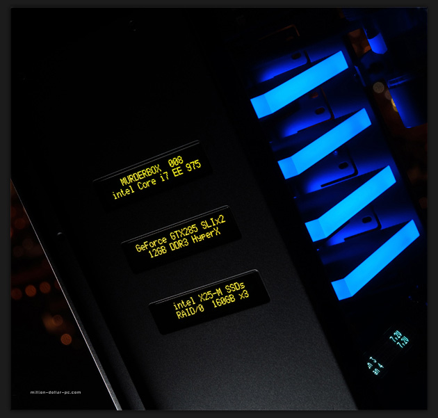
The MurderBox is using what type of LCD ? 16x2 Character LCD or 20X4 Character LCD ? One USB can connect how many LCD ?
*
If you count the longest text display on the LCD, it is around 20 characters... but have 2 lines only... 20 x 2 type or longer...

I think he is using a uncommon LCD module ...

From the URL, I saw that the fellow hv another LCD inside the case to display all the temp and such and the three LCD at the front are static LCD only..

So my guess is that those 3 LCD are static display only and the text does not change ... no need to use USB, just wire up a microcontroller to the LCD, send the codes/programming to the microcontroller with the text

line 1 " Super Duper Mod 002"
line 2 "Intel Core i 7 xx 888"

and power it up from the +5V molex with some resistors.. totally not connected to the PC at all...

When you need to change the text, just plug in the USB/Serial TTL and re-programme it... I've an article on my blog/facebook page on it..

Each Arduino microcontroller could drive like 1 LCD bcos each LCD would take up 3 control pins and 4 data pins...

If you needed 3 Arduino for this purpose with LCD module, I can make them for you cheaply if you are intertested...


Added on December 26, 2010, 10:23 am
QUOTE(limhongwoon @ Dec 25 2010, 07:42 PM)
user posted image

The MurderBox is using what type of LCD ? 16x2 Character LCD or 20X4 Character LCD ? One USB can connect how many LCD ?
*
If you count the longest text display on the LCD, it is around 20 characters... but have 2 lines only... 20 x 2 type or longer...

I think he is using a uncommon LCD module ...

From the URL, I saw that the fellow hv another LCD inside the case to display all the temp and such and the three LCD at the front are static LCD only..

So my guess is that those 3 LCD are static display only and the text does not change ... no need to use USB, just wire up a microcontroller to the LCD, send the codes/programming to the microcontroller with the text

line 1 " Super Duper Mod 002"
line 2 "Intel Core i 7 xx 888"

and power it up from the +5V molex with some resistors.. totally not connected to the PC at all...

When you need to change the text, just plug in the USB/Serial TTL and re-programme it... I've an article on my blog/facebook page on it..

Each Arduino microcontroller could drive like 1 LCD bcos each LCD would take up 3 control pins and 4 data pins...

If you needed 3 Arduino for this purpose with LCD module, I can make them for you cheaply if you are intertested...


This post has been edited by stan001: Dec 26 2010, 10:23 AM
TSstan001
post Dec 27 2010, 05:54 PM

On my way
****
Senior Member
623 posts

Joined: Jan 2003
From: Kuala Lumpur


It is cheaper to buy a LCD module than to salvage from a calculator...

Anyway, the calculator is numeric, not alphanumeric..


TSstan001
post Dec 28 2010, 02:41 AM

On my way
****
Senior Member
623 posts

Joined: Jan 2003
From: Kuala Lumpur


QUOTE(techi5 @ Dec 28 2010, 12:57 AM)
what about a touchscreen lcd from besta dictionary? mine's broken, but i'm 100% sure the lcd is working smile.gif can?
*
Are you able to get the specs or datasheet of the LCD used in the besta ?

The ones Arduino usually use are all using HD44780-compatible LCD ..

More of the type of display supported at : http://www.arduino.cc/playground/Code/LCD

All the supported ones will have its libraries..


2 Pages  1 2 >Top
 

Change to:
| Lo-Fi Version
0.0242sec    0.24    7 queries    GZIP Disabled
Time is now: 26th November 2025 - 08:31 AM