QUOTE(kww @ Jan 21 2009, 07:52 PM)
Can anyone teach me what value of component and connection should be for:
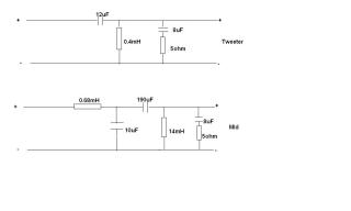
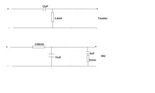
- 4ohm tweeter to High pass at 2kHz
- 4ohm mid bass band pass at 50Hz to 2kHz
Thanks.
hi there,
well i wish it was that easy, BUT you have to calculate the values based on thiel/small parametres.
eg, if your 4 ohm tweeter has a sensitivity of 92db and the woofer had a sensitivity of 89db you need to pad your tweeter 3db to have a nice even output. padding is where you need a resistor either in series or an L pad (2 resistors to bring your tweeter level down to match the woofer).
then you need to take into consideration the on axis response, 30 degrees off axis response 60 degrees off axis response as well.etc. etc.
then with the woofer you need to know the response curve ie break up nodes in the response and where best to cross it over, the fs, the qts, the x-mas, the VAS, the voice coil inductance at selected crossover point, how to add a zoebel network, the actual application of the woofer has to take into even more considerations. as well as designing a volumus cabinet best suited to the woofers parametres.
all these things add up into the crossover and ulimatley the full speaker design.
but if you wanted to just do a calculation that would
not take all these into the design then you use this for simple crossovers.
Crossover Component Selection Guide
High Pass
Crossover
Frequency
6 dB/octave 12 dB/octave
4 ohm 8 ohm 4 ohm 8 ohm
C1 in uF C1 in uF L1 in mH C1 in uF L1 in mH C1 in uF
500Hz 79.60 39.80 1.801 56.270 3.601 28.135
700Hz 56.86 28.43 1.286 40.193 2.572 20.096
1,000Hz 39.80 19.90 0.900 28.135 1.801 14.067
1,500Hz 26.53 13.27 0.600 18.757 1.200 9.378
2,000Hz 19.90 9.95 0.450 14.067 0.900 7.034
2,500Hz 15.92 7.96 0.360 11.254 0.720 5.627
3,000Hz 13.27 6.63 0.300 9.378 0.600 4.689
3,500Hz 11.37 5.68 0.257 8.039 0.514 4.019
4,000Hz 9.85 4.98 0.225 7.034 0.450 3.517
4,500Hz 8.84 4.42 0.200 6.252 0.400 3.126
5,000Hz 7.96 3.98 0.180 5.627 0.360 2.813
Low Pass
Crossover
Frequency
6 dB/octave 12 dB/octave
4 ohm 8 ohm 4 ohm 8 ohm
L1 in mH L1 in mH L2 in mH C2 in uF L2 in mH C2 in uF
75Hz 8.49 16.99 12.00 375.132 24.00 187.566
100Hz 6.37 12.74 9.00 281.349 18.00 140.674
150Hz 4.25 8.49 6.00 187.566 12.00 93.783
200Hz 3.19 6.37 4.50 140.674 9.00 70.337
250Hz 2.55 5.09 3.60 112.540 7.20 56.27
300Hz 2.12 4.25 3.00 93.783 6.00 46.891
350Hz 1.82 3.64 2.572 80.385 5.145 40.193
400Hz 1.59 3.19 2.251 70.337 4.502 35.169
450Hz 1.42 2.83 2.00 62.522 4.00 31.261
500Hz 1.27 2.55 1.80 56.270 3.60 28.135
700Hz .91 1.82 1.286 40.193 2.572 20.096
1,000Hz .637 1.27 0.900 28.485 1.804 14.067
1,100Hz .579 1.16 0.818 25.577 1.637 12.789
Explanation
Using the charts
The chart above is for calculating 6dB and 12dB crossovers. For higher crossover points than those shown, simply move the decimal point to the right one place to match the new frequency, find the capacitor and inductor values and move their decimal point one place to the left. For example: If you desire a high-pass crossover frequency of 50 Hz for a 12 dB crossover for 8 ohms, find the 500 Hz listing. Locate capacitor and inductor values and move their decimal one place to the right. The correct values would then be 36.01 mH and 281.35 µF. Example 2: if you desire a low-pass crossover frequency of 50 for a 6 dB crossover for 4 ohms, find the 500 Hz listing. Locate the inductor value and move it's decimal to the right, making it 12.7 mH.
Tolerances
When looking for capacitors and inductors, keep in mind that the tolerances of the components can help simplify your search. For example: The calculation chart finds 281.35 to be the exact capacitor value for the above crossover. If you're looking through the Non-Polarized Crossover Capacitors, their tolerance is 10%. This means that the actual measured value of each capacitor is within 10% of the listed value, in this case ±28 µF. So, adding 250 µF and 33 µF in parallel to achieve 283 µF, considering the tolerance, will put them somewhere between 255 and 311 µF, which is suitable for the application. For example 2, if you're looking in the 18 gauge, Perfect Layer Wound Air Core Inductors, their tolerance is ±2%. The calculated value of 12.7 mH could be suitably achieved using a 12.00 mH inductor, whose 2% tolerance puts its actual value between 11.76 and 12.24.
Combining Components To Achieve Needed Values
If you are unable to find larger component values, components may be added together to yield the desired values. To add capacitor values, they can be connected to each other in parallel. For example, if a value of 500 µf is needed, two 250 µf caps can be connected such that both sets of leads are connected.
so good luck but dont waste expensive drivers if your not going to integrate them with all the considerations of a full speaker design.


 Jan 13 2009, 08:26 PM
 Quote
Quote


 0.0238sec
 0.82
0.82
 6 queries
 GZIP Disabled