Welcome Guest ( Log In | Register )

4 Pages < 1 2 3 4 >Bottom

Outline · [ Standard ] · Linear+

PC Audio Creative GigaWorks S750 7.1 speaker repair, A short guide and info with pictures...

views
     
TSlex
post Feb 16 2014, 01:43 PM

Old Am I?
Group Icon
VIP
18,182 posts

Joined: Jan 2005
From: Dagobah
QUOTE(watermineral @ Feb 16 2014, 06:08 AM)
edifier s330, same problem also, constant noise, but the sound more like duuuuuuu....  rclxub.gif

http://www.youtube.com/watch?v=m2yBSXv0gc0...player_embedded
*
Could be either the power supply section and/or audio power amplifier section. Hard to say until examined closely the internals... hmm.gif

QUOTE(chrislue @ Feb 16 2014, 11:14 AM)
I just checked the stock caps I pulled out, found out that almost every copper tubes inside through holes have also been pulled out with caps leads. blink.gif

Looks like I have to use the "L" way to fix them all.
Can ignore the leads that are connected to the bottom side, just repair the leads that are connected to the top side. Check carefully the location to place the "L" wire on the top as to prevent unwanted connections. wink.gif

QUOTE(chrislue @ Feb 16 2014, 11:14 AM)
Is there any good way to avoid this? I tried use solder sucker, didn't work very well, so basically I just melt the solder and then pull out caps by force.  icon_question.gif
*
If use that method, then pull them by tilting the capacitor side to side with one lead/leg at a time. The problem is that there is solder between the leads/legs of the capacitor and the tube surface inside that still remained. Usually can be pulled out easily but if the leads/legs are tight inside the hole then the soldering iron had to stay a little longer (to completely melt the solder inside the hole), and that usually can result in the tubes and solder pads coming off due to prolonged heating (as the soldering iron melts the glue than holds them in place). And yeah, desoldering double sided board can sometimes be very difficult as well, especially when there is solder still inside the through hole. The most recommended tool for this type of job is: HAKKO | Desoldering / Rework | HAKKO 808 which is rather pricey but gets the job done. Example of real word usage... icon_rolleyes.gif
» Click to show Spoiler - click again to hide... «


This post has been edited by lex: Feb 16 2014, 01:44 PM
TSlex
post Feb 22 2014, 07:02 PM

Old Am I?
Group Icon
VIP
18,182 posts

Joined: Jan 2005
From: Dagobah
QUOTE(chrislue @ Feb 16 2014, 06:24 PM)
I still have another question, since I haven't replaced other small caps yet. For those you mentioned choosing low impedance and/or low ESR types, how much difference is between a high one and a low one? Like for 100uf 35v, between an United Chemi-Con GXE series  340mA 320mOhm and a Nichicon PW series 555mA 117 mOhm? Do they make a big difference? What's the max acceptable impedance or min ripple current?
*
For those capacitors after the voltage regulators, any low impedance capacitors will do. The main purpose is to filter out remaining ripples from the voltage regulator and rectifier stage (which could have slipped the first hurdle). Those Nippon Chemi-con GXE series have higher operating temperatures (up to 125C) targeted for harsh and very hot environments such as inside car engines (and should be also suitable for this speaker system). Generally prefer capacitors that can handle high ripple currents and also low impedance as well. wink.gif

QUOTE(chrislue @ Feb 21 2014, 11:48 AM)
Bad news, one of my S750 blew again, first time after I repaired it it's OK, played some music for several minutes, second time blew when doing some volume adjustments in windows . I checked it, same parts blew, a R30 resistor blew, turn to black, along with a diode d24 (a 15v zener replaced last repair), no visual damage, other parts seem ok.

What could caused this?
*
Is that R30 resistor have a value of 100 Ohms? What was the wattage of the resistor and zener diodes? Do note that both resistors and zener diodes have wattage ratings. If too small wattage then it may blow (due to overheating and conducting electrical current past specifications). Check the pins at the transformer for cold solder joints. There may be a weak MOSFET in the other side/half of the circuit (which could be damaged in the first failure). Thus replace those with new ones as well. Also check that fusible link (0 Ohm resistor). Anyway, did you remove all the degraded glue and replace all the capacitors as mentioned here? hmm.gif

This post has been edited by lex: Feb 22 2014, 07:03 PM
TSlex
post Feb 24 2014, 01:16 PM

Old Am I?
Group Icon
VIP
18,182 posts

Joined: Jan 2005
From: Dagobah
QUOTE(chrislue @ Feb 23 2014, 02:02 AM)
Yes, R30 is a 100Ohms 1/4 W resistor, and the zener is 15v 500mW (1/2 W), should I replace R30 with a 1/2 W? I forgot to mention I also changed a mosfet IRF740 Q4 which is connected with R30 in first repair, I don't know if it is failed this time since I don't know how to check a mosfet. R3 and R32 (0 Ohm resistors) are OK.
Try using higher wattage parts, plus check D16, R39, C30 and C58 (replace all of them if necessary). Also on the other half, replace Q1. As for the R31 (fusible link or zero Ohm resistor), make sure it has no resistance at all (virtually zero Ohms). Do inspect carefully for possible cold/cracked solder joints on the transformer pins. Re-check the L links on the through hole repairs (make sure the top side has sufficient solder and contact with it)... hmm.gif

QUOTE(chrislue @ Feb 23 2014, 02:02 AM)
I have removed all the glue and replaced all the capacitors, same ones you used in your repair.
*
Make sure all degraded glue has been cleanly removed especially the feedback areas, and places there there are exposed traces and solder pads. Clean with isopropyl alcohol also, as sometimes the chemicals from the degraded glue breaking down may remain on the surface (will look like stains, and is usually conductive and/or corrosive!). icon_rolleyes.gif

This post has been edited by lex: Feb 24 2014, 01:20 PM
TSlex
post Mar 3 2014, 09:41 PM

Old Am I?
Group Icon
VIP
18,182 posts

Joined: Jan 2005
From: Dagobah
QUOTE(chrislue @ Feb 25 2014, 05:32 AM)
From the schematic, I can tell C30 is 220pf 1kv, D16 is 1n4148, but what about C58? 3300pf? what is the voltage?
*
For most of these switching type power supply circuits, especially close to any choke or transformer (such as those used as part of snubber network), the voltage rating of the capacitor should be around at least 1kV (usually to account for any forward and/or back EMF which has usually higher voltage than the supply rail). For that C58, just try using one 3.3nF capacitor with 1kVDC rating (although it looks to be main part of an oscillator startup/feedback loop)... hmm.gif

QUOTE(andrew9292 @ Feb 25 2014, 01:03 PM)
I noticed that some film caps have a VDC or VAC or just V rating for voltage.
Do this ratings play a role for coupling capacitors? (2.2 uf 50V caps on Edifier M3300 changing to film caps)
*
Hardly matters here anyway as even the audio signal is very low (typically under 2VRMS) and well below 50V peak level (of course not surpassing the voltage of the power supply). The bias voltage held at these capacitors is about half the voltage of the supply rails which is pretty low (again, much lower than 50V)... wink.gif

QUOTE(jviojtaba @ Feb 26 2014, 05:30 AM)
hi , at first my s750 just wont turn on and i fix them after that i got 2 cap exploded !
i change them and right now its working as power supply !
but all of my speakers have a low sound and distorted sound i don't know where is the problem exactly,
so i just ask for it if anyone have this problem and know which part of amp make this problem
just tell me and i will find a way to fix it tnx , i keep looking forward to found a way to fix the problem .
if any photo needed i can bring the photos just ask me .  sad.gif
*
First, check what was the voltage output at the main power section (for the power amplifier section). Did you change all the capacitors as shown here? Also check for faulty components, especially that fusible link (zero Ohm resistor) at the main power section... icon_rolleyes.gif

TSlex
post Jun 15 2014, 02:38 PM

Old Am I?
Group Icon
VIP
18,182 posts

Joined: Jan 2005
From: Dagobah
QUOTE(Audison @ Mar 19 2014, 02:58 AM)
Hi Lex and others posting in this thread! I just wanted to say Thank you! to all of you for making information about this sound system available as it helped tremendously when fixing my set of S750. I would probably never dared to open it, if it was not for this thread that give me all information i needed about the components and other stuff. I am not an expert in this field so apologies if i am going to be asking very basic stuff that anyone should know. I already replaced all the capacitors that was recommended in this thread but i need to replace one resistor that has died but i can't really read the colors down and all the measuring does give me not really clear idea of what resistance he is. i am going to attach an image or the picture that was posted above with my resistor marked. Thanks again for all your help. notworthy.gif
» Click to show Spoiler - click again to hide... «
*
Its 22 Ohms. That resistor is part of a RC snubber network around the recitfiers. I would recommend Google "resistor color code" to find references to resistor values, as well as online resistor color code calculators. nod.gif

QUOTE(Mikoman @ May 8 2014, 09:00 PM)
Hi Lex, all,

Thanks for amazing tutorial. I fixed my s750. This is awesome.

I have replaced all capacitors with panasonic ones. I wonder if there is something wrong or it's normal behavior but the "L" type cooler on the power board (the one near big capacitors) is extremely hot even when i listen the music on low volume. So i added another massive cooler (marked with red arrow) to it and seems a lot better now but still hot. I quess that's why they used 105 degrees capacitors smile.gif
» Click to show Spoiler - click again to hide... «
Well, a fan mod would do better to cool down the components though would be more work than just attaching an extra heatsink. I've had another one repaired not long ago. Not as pretty as the first few shown here (due to very stubborn degraded glue).. cool2.gif
» Click to show Spoiler - click again to hide... «

QUOTE(Mikoman @ May 8 2014, 09:00 PM)
I had the same issue like Galeak with immediate power of after a power on so i ordered those DB3 for replacement. So hopefully it will help.
Anyways after the replacement of all capacitors the green light was ok but the red light on the remote was death. I searched a little bit and found this
THE PROBLEM WITH THE ?CONTROL POD IF NO WORK, ONLY OPEN USING SCREWDRIVERS
LOOK ONE MICROCHIP ?M34502E4FP?, MAIBE CPU IT IS IN RESET STATE. THE ONLY THING YOU HAVE TO DO IS GET A SOURCE WITH 5 VOLTS DC AND PUT THE NEGATIVE LINE IN THE PIN 2 COUNTING SINCE MARK AS NUMBER AND THE POSITIVE LINE (+) ?IN THE PIN 6 IT IS THE RESET, IF NO ON RED LIGHTS IN THE CONTROL POD PUT THE POSITIVE LINE IN THE 7 PIN THIS PIN IS P2Ain THATS SUPPLY 5V DC TO DE STAND BY BUTTON MANUALLY AND RESET DE POD.
NOW RETIRE THE SOURCE OF 5V OF THE PINS AND THE POD IS WORKING NORMALLY. BE CAREFULL PUTING LINES (+) AND (-) ON THE PINS OF THE MICRO THAT NO JUMP WITH ANOTHER PINS.
HOPE THAT SOLVE THE PROBLEMS.

And this solved my problem (i did both steps with pin 6 and 7). Hope it will help to someone as well.

Cheers
*
Have not yet encountered such problematic control pods, though the usual problems I've encountered is the glitchy standby button (which causes quick on-then-off sometimes) due to worn microswitch inside. The other one, was the stuck volume button caused by misaligned plastic contact internally (can be fixed easily). As for the problem described above, thanks, will look into it when/if I've encountered one of these... hmm.gif
TSlex
post Jun 20 2014, 08:11 PM

Old Am I?
Group Icon
VIP
18,182 posts

Joined: Jan 2005
From: Dagobah
QUOTE(spenceg @ Jun 20 2014, 03:08 AM)
You are clearly a legend and have a lot of knowledge.  I also have issues, but would like to hear you live in the UK, so I can pay you to fix my unit!

Here is hoping?!
*
Unfortunately I'm not living in the U.K. You may try finding someone with electronics repair experience (ie. good with soldering jobs) to help you from your own country at Badcaps... hmm.gif

This post has been edited by lex: Jun 20 2014, 08:12 PM
TSlex
post Jun 23 2014, 02:01 AM

Old Am I?
Group Icon
VIP
18,182 posts

Joined: Jan 2005
From: Dagobah
QUOTE(spenceg @ Jun 22 2014, 11:13 PM)
It can handle the soldering, but I feel out of my depth working out what is wrong i.e. on a visual inspection all looks good (although maybe one questionable diode).
As mentioned in this thread, first steps would be to replace those capacitors and clean up all the degraded glue (including those on the other boards besides the power supply one). Sometimes bad capacitors do not necessarily bulge/bloat. They can be also be leaking from the bottom, and/or simply became "dried" without any apparent signs. As for other failed and/or faulty components, then you have to look/observe carefully and may require some tools (such as a multimeter, plus some knowledge on diagnosing/checking for failed/faulty components). For some components, you may need to pull it out to check (ie. cannot be checked in circuit itself).. hmm.gif

QUOTE(spenceg @ Jun 22 2014, 11:13 PM)
So what happened?  Firstly I had that blinking green light issue, where there are enough internet posts saying use a hairdryer to heat it up (which is what I did).  Afterwards when turned on the small box power (after a steady green light of 24 hrs or so), there was a pop and now the sound is all distorted/crackly.  I am not sure how to diagnose or on what board the problem would be.
That hot air treatment is not recommended at all, and will eventually kill the subwoofer (which is what happened to the original person who posted that "quick fix", his subwoofer finally went kaput). That only works if there are dying/failing capacitors on the power supply. For your information, when capacitors start failing their capacitance is becoming reduced. Heating up electrolytic capacitors will increase its capacitance, thus "restores" some capacitance to allow the power circuits to continue to function. However in the long run, heating up those capacitors will cause the electrolytes inside to boil and degrade, thus finally goes bad and the subwoofer stops working altogether. Also heating up the boards inside the subwoofer dries up and evaporates the conductive chemicals from the degraded glue. This restores normal circuit functions. However as the degraded glue continue to decay and breakdown, more conductive chemicals are produced and causes circuit confusion (due to creation of "phantom circuits"). Using that hot air heating it up only temporarily restores some circuit functions (until the next round). Please note that direct heating can also damage (and degrade) other components as well... wink.gif

QUOTE(spenceg @ Jun 22 2014, 11:13 PM)
If you have ideas, I can test and also post photos, but where to start.

thanks in advance.
*
Some photos may help. What is your level of electronics knowledge? In particular, checking for failed/faulty components? unsure.gif

This post has been edited by lex: Jun 23 2014, 02:10 AM
TSlex
post Jun 25 2014, 02:37 PM

Old Am I?
Group Icon
VIP
18,182 posts

Joined: Jan 2005
From: Dagobah
QUOTE(hiwnik @ Jun 24 2014, 07:40 PM)
Hello! I from Ukraine, sorry for my English. I have broken Creative GigaWorks S750 7.1 speaker system. I need your help. I followed for your advise and ordered complete set of capacitors but I found some diodes broken. Can You prompt me technical descriptions and analogues to these diodes: D6, D7, D8, D22, D23, D24 и D25. In the schematic (circuit) diagram for power board I found only D8 - 1n4148, and on other the detailed information is not present.
Both D6 and D7 are DIACS. The part number is "BR100/03" and you should be able to find it on most online stores. D22, D23, D24 and D25 are actually a 15V zener diode. Can just choose any available 15V zener diode (and preferably with higher wattage), for example "1N4744A"... icon_idea.gif

QUOTE(hiwnik @ Jun 24 2014, 07:40 PM)
Similarly discovered that at a few resistors resistance below set approximately on 40%: R19, R21, R22, R10, R33, R31. I found out the set resistance, but I would like to know, on what yet to pay attention at their replacement (firm-producer, tension).
Thank you for your useful advices. I wait an answer. smile.gif
*
Resistors should not be 40% off (that's too much). The most I would tolerate would be 10% off, and the most recommended tolerance is 5% or lower. Thus do check those resistors again. Anyway some of those resistors mentioned are simply 0R (zero Ohm) links such as R31 and R10 thus your measurement could be off due to the error offset on your meter. Thus do check the error offset of your meter, as it could have caused incorrect readings. As for properly measuring the resistors, you have to remove them off the board first otherwise surrounding connected components (including other resistors) could affect the measurement... hmm.gif

QUOTE(Quazacolt @ Jun 25 2014, 01:21 AM)
woah didn't expect someone from Ukraine to register just for this speaker. sifu lex need to entertain already laugh.gif
*
They (Creative Labs) no longer make beasts like these anymore. This GigaWorks S750 subwoofer is capable of reproducing frequencies below 35Hz or below 40Hz (the lowest frequency which most run-of-the-mill subwoofers are capable of), as mentioned in its specifications a very low 25Hz... cool.gif

This post has been edited by lex: Jun 25 2014, 02:50 PM
TSlex
post Jun 27 2014, 08:42 PM

Old Am I?
Group Icon
VIP
18,182 posts

Joined: Jan 2005
From: Dagobah
QUOTE(hiwnik @ Jun 27 2014, 01:24 AM)
Thanks for your detailed answer. Resistors really showed other indicators after their removal. But I will buy a new one resistor, as when trying to solder it into, he slipped out of the tweezers and lost  smile.gif . I would also like to clarify: a diode D12 – is same 1N4004?
*
The run-of-the-mill 1N4004 is just a normal/standard diode thus not suitable. That D12 is right after the transformer and this is a switching type power supply, thus you have to use either a schottky diode or a fast recovery diode. In other words, not the same... wink.gif

This post has been edited by lex: Jun 27 2014, 08:44 PM
TSlex
post Jul 22 2014, 07:26 PM

Old Am I?
Group Icon
VIP
18,182 posts

Joined: Jan 2005
From: Dagobah
QUOTE(Cookie000 @ Jul 22 2014, 12:33 PM)
Great guide Lex! thumbup.gif
Here's my board after 10 years of owning the s750. 4 bulged 470uF caps(yes all 4) still power up as normal with very looooow volume. Like not enough juice to power the amps.
Did you managed to fully revive the unit? Does it still suffer from very low volume after repairs? Check those 0R resistors situated right behind those big four 470uF 200VDC capacitors, in case the low volume problem still remains... hmm.gif

QUOTE(Cookie000 @ Jul 22 2014, 12:33 PM)
» Click to show Spoiler - click again to hide... «
Stupid glue did a lot of damage except in the second pic. cry.gif
» Click to show Spoiler - click again to hide... «
*
Looks like quite an amount of oxidation there (by the chemicals from degraded glue) as the copper layer looks dark and/or dull, instead of being shiny. After removing all those chunks degraded glue, try cleaning those exposed spots with IPA (isopropyl alcohol) to remove any remnants of chemicals from the decaying glue... wink.gif

This post has been edited by lex: Jul 22 2014, 07:28 PM
TSlex
post Aug 26 2014, 11:05 PM

Old Am I?
Group Icon
VIP
18,182 posts

Joined: Jan 2005
From: Dagobah
QUOTE(Shadowdace @ Aug 26 2014, 10:40 PM)
Hi ppl, Hi Lex
First of all, ty for this epic topic, i'm learning alot and mb will have a chance to save my s750 too.
Now here is my trouble:
I've the same typical meltdown aka flashing green light and brown glue of death. I tried to remove it painfully and regulary test it. Obviously I made a short circuit and both of my c40 blown out  shocking.gif
Now I'm on my way to change all part Lex recommended but I've a doubt about this c40: Kukruse said It's a 100v cap but his reference links to a 50v cap (in parlist.doc)
I'm already extremely lost in the number of parts and nomenclature, I hope you can help me with this c40 (or an exhaustive list for the whole pack sweat.gif but I can deal with research)
Ty in avance
*
C40? Is that a ceramic disc capacitor? If it is then usually that is 10nF (or 10,000pF) and the recommended voltage rating is usually 1kV since its part of the snubber network around the rectifiers... hmm.gif

TSlex
post Aug 27 2014, 02:02 AM

Old Am I?
Group Icon
VIP
18,182 posts

Joined: Jan 2005
From: Dagobah
QUOTE(Shadowdace @ Aug 26 2014, 11:41 PM)
It's the orange one burned here:
» Click to show Spoiler - click again to hide... «
in the post of Kukruse https://forum.lowyat.net/topic/2873671/+80#Is his partlist.doc looks good to you?
My studies in science and technical engineering are soooo gone  cry.gif
*
This is one of the power amplifier boards, and there are two of them. In fact both of them are identical. You can check the value of the capacitor on the other power amplifier board, in the same location. If that capacitor is in parallel with that big (1000uF 100VDC) electrolytic capacitor next to it, then very likely its a 100nF capacitor with voltage rating of at least 100V (following the big capacitor, can use capacitors with higher voltage rating also). Anyway, that capacitor may not be the only failed component on that board. Possibly that big (1000uF 100VDC) electrolytic capacitor next to it has some problems as well... hmm.gif

TSlex
post Aug 27 2014, 09:35 PM

Old Am I?
Group Icon
VIP
18,182 posts

Joined: Jan 2005
From: Dagobah
QUOTE(Shadowdace @ Aug 27 2014, 09:12 PM)
Ok thanks a lot! It should be the FK20X7S2A475K whitch is described as a 100v than the  FK20X7S1H475K (50v) witch is on partlist.doc
This one is a 4.7uF 100V ceramic capacitor. It should follow the same voltage as that big capacitor next to it... hmm.gif

QUOTE(Shadowdace @ Aug 27 2014, 09:12 PM)
Btw I'll change every old/bad lytics and glue before re trying. This glue is awfully stuck on board, I'm scared of scratching something...
*
The one to get rid off are those that have turned yellowish to brownish color. The white colored glue is still fine, as its a different type of glue than the ones used on the rest of the boards... wink.gif

TSlex
post Aug 29 2014, 01:01 AM

Old Am I?
Group Icon
VIP
18,182 posts

Joined: Jan 2005
From: Dagobah
QUOTE(Shadowdace @ Aug 29 2014, 12:14 AM)
I don't understand very well the condensator's role. The FK20X7S2A475K seems good but it's very difficult to buy. What did I have to check for a new one? Same size and voltage obviously (100V like the big one on the pic) and 4.7 µF like the parlist of Kukruse. Is that all? I don't know the difference betwin ceramic and lytics..
*
Actually you can use just any ceramic capacitor of the same capacitance (4.7uF) and voltage rating (100VDC). Typically I would choose NP0/C0G, U2J, X7R and X8R type ceramic capacitors (more stable across entire range of temperatures) rather than the cheaper Z5U and Y5V ceramic type capacitors (capacitance and impedance varies a lot with temperature). That big capacitor beside it is a general purpose capacitor. Usually if you find a ceramic capacitor in parallel with it then its one way which some manufacturers cut cost. Instead of using more expensive specialised low ESR/impedance capacitors, they would use cheaper general purpose capacitor with a cheap ceramic capacitor. The strength of ceramic capacitor is that it has very low ESR/impedance at high frequencies (typically in the switching power supply range). Thus that capacitor serves as a low ESR/impedance side to the bigger electrolytic capacitor (functions to bypass/filter and sink high frequency ripples off the rails that the bigger general purpose electrolytic capacitor unable to handle). And if the power rails are too noisy (often due to power supply failing) then that ceramic capacitor will be taking all the "heavy load" (trying to remove the ripples)... icon_rolleyes.gif

This post has been edited by lex: Aug 29 2014, 01:06 AM
TSlex
post Sep 6 2014, 01:49 AM

Old Am I?
Group Icon
VIP
18,182 posts

Joined: Jan 2005
From: Dagobah
QUOTE(Shadowdace @ Sep 5 2014, 12:31 AM)
Hi Lex
I would be eternally grateful for your help, everything works!  thumbup.gif
I actually changed the big cap 450V on C61 and the cap 0.1µF 50V on C63 who are both dead (nothing on multimeter), C62 and C68 (they suffer too much from the proximity of the sink) and obviously I got rid off this glue (one off the most painfull work i've done  vmad.gif 
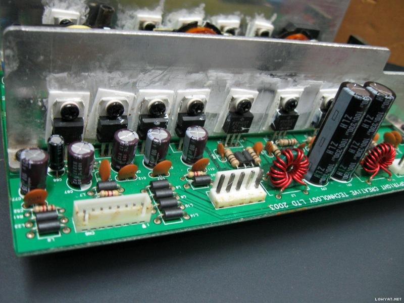
). On the amp board I've changed C40 (totally burned out), C39 (sligtly burned by C40), C81 and 91 glued to death...
Still have to replace the five 220µF and the five 100µF but It works!
Glad it worked. Should give those speakers a new lease of life... wink.gif

QUOTE(Shadowdace @ Sep 5 2014, 12:31 AM)
Btw, I found the same problem I've before: The rear left output is down and I've some kind of cut in sound at higher level (above mid power depend of source) like a saturation. I can live without taking down the neighborhood's trinket but one way down is problematic...

Oh and thanks again for your advice that helped me so much ^^
*
Have you cleaned the connectors on the power amplifier boards? Also you may have to clean the audio controller board and the I/O board (where the audio, control pod/dock and speaker connectors are located). Especially the I/O board, which is right under the audio controller board, has lots of degraded glue especially at the connector solder pins. That one is kinda hard to clean and require some proper tools... hmm.gif
TSlex
post Sep 6 2014, 11:00 PM

Old Am I?
Group Icon
VIP
18,182 posts

Joined: Jan 2005
From: Dagobah
QUOTE(Shadowdace @ Sep 6 2014, 04:39 AM)
I cleaned everything I could reach: Powerboard of course, degraded glue on both aux board (part brown, part white) and I cut the glue connexion between lytics on audio controller board (which is indeed the one on top with forty capacitor?). Some of the lytics still glued but no short circuit anymore.
Below audio controller, the I/O board contains two massives plates of glue: One top of the jack's enter, the other links the seven dual cable (red&black). This part requires desoldering the CN2 and CN4 line that I'm a bit afraid to do...
» Click to show Spoiler - click again to hide... «
Do you think the soud's cut/saturation could come from C59/60/69/70 (or the 10 caps 220µF and 100µF on amp board) I have not change?
*
Yups, those are the boards I've mentioned. Particularly that I/O board is just full of glue. I would recommend that you scrape it off, as there could be degraded glue hidden under it (and causing problems with some of the audio inputs there). If you do not want to desolder the board off (which is a lot of hard and difficult work, particularly since this is double sided PCB) then try usuing a thin long flat head screwdriver plus very fine but strong tweezers to remove those glue. Also remove any glue on the audio controller board especially those that cover the I.C pins. Have to be delicate as these are (delicate) SMD type components thus proceed with care and caution... sweat.gif

TSlex
post Sep 16 2014, 12:57 AM

Old Am I?
Group Icon
VIP
18,182 posts

Joined: Jan 2005
From: Dagobah
QUOTE(thebundok @ Sep 15 2014, 04:14 AM)
Hey Lex,
Really glad I found this thread as I'm really reluctant to give up on my S750's. Quite impressed that you've kept it going for over a year! Recently had a power outage at the house and the power kept trying to come back on. After the power finally returned for good, I had the dreaded pulsing green power light which then became no light. No power to the control box and no sound at all. cry.gif

I should preface that I'm a complete newb at this electrical engineering stuff. Aside from a little experience soldering an "Ultimate Useless Machine" I haven't really done much and I've never had experience with finding faults on a PCB. I can't find any capacitors that have bulged but since you mentioned they're low quality I figured I'd replace them anyway and hope it fixes the problem. Would you mind taking a look at this project order on Mouser just to ensure that I followed your recommended replacements well?
First off, that 470uF 200VDC capacitor is of wrong dimensions. Its too tall at 50mm. Plus the originals are "snap-in" types. Thus please follow of the capacitors I've selected, which should be this one: Mouser > Passive Components > Capacitors > Aluminum Electrolytic Capacitors > Aluminum Electrolytic Capacitors - Snap In > Panasonic EET-ED2D471BA. And looks like that one is going to be EOL'ed (thus grab it while still available, because that one has one of the best specifications compared to the rest of the field)... nod.gif

QUOTE(thebundok @ Sep 15 2014, 04:14 AM)
One piece I noticed that seems a little off, which maybe you can comment on, are the resistors(?) at D8 & D13 (circled in the first photo). If they're supposed to look like D7 and D6 then they look like they're possibly burned out. If you agree, can you enlighten me as to what type of resistors those are? They don't follow the normal convention I'm used to seeing of colored bands on beige.  blush.gif
Those are not really resistors. Sometimes they are called 0 Ohm resistors (single black band means "0"), but they are actually fusible links (that looks like resistors)... tongue.gif

QUOTE(thebundok @ Sep 15 2014, 04:14 AM)
You mention a lot about removing the old glue, and I'm all but finished cleaning all the old bits of glue off (still a work in progress), but you don't mention anything about re-gluing. Is this something we should do after replacing capacitors? If so, how is that done? Honestly the board looks better without the glue so I'd be just fine leaving it off of there.
I've included some photos for your viewing pleasure. Thanks again for this post! I've found it incredibly helpful and enlightening. biggrin.gif
» Click to show Spoiler - click again to hide... «
*
That glue to help hold the components (especially big ones) in place for easier soldering (in the factory). Other than that it has no use at all. Thus just remove those glue. And do not use anymore glue. The prolonged heat inside the subwoofer can degrade (cause chemical breakdown) those glue. Do clean with IPA (isopropyl alcohol) the areas where the glue was removed... icon_rolleyes.gif
TSlex
post Sep 16 2014, 11:34 PM

Old Am I?
Group Icon
VIP
18,182 posts

Joined: Jan 2005
From: Dagobah
QUOTE(thebundok @ Sep 16 2014, 05:50 AM)
Thanks for such a quick reply!  notworthy.gif
Wow, thanks for catching that. I thought I was being so careful, there were a few different links around this thread and I wasn't sure about the End of Life thing.  doh.gif
Seems Panasonic decided to quit producing snap-ins. That Panasonic TS-ED series (actual datasheet here) has the best specifications among all, with ripple current handling of 1850mA@120Hz while the rest of the field have around 1400mA to 1600mA ripple current handling only (at 120Hz). Alternatives would be Nichicon GU series (which has lower ripple current handling)... nod.gif

QUOTE(thebundok @ Sep 16 2014, 05:50 AM)
Thanks for clarifying. In your opinion do they also need replacing? If so, is this what I'm looking for?  unsure.gif
If they are not broken (should read as shorted on the multimeter) then no point replacing them. Yes, those are the "0 Ohm" resistors (actually fusible links)... wink.gif

QUOTE(thebundok @ Sep 16 2014, 05:50 AM)
And one last curiosity question. When I bought the speakers, nearly 10 years ago, I was living in the US. Now I'm living in Europe. Is it possible to convert the sub to 220V and if so is it fairly easy to do? Is it possible to make it dual-voltage? 110-220V?  hmm.gif  (according to the input it's already 110-120V 50/60Hz)
*
That standby power section may be able to automatically adjust to new higher voltage (since its a standard flyback design), but the main power section may not be able to use a higher voltage (does not seem to have any feedback section). hmm.gif
TSlex
post Sep 26 2014, 12:03 AM

Old Am I?
Group Icon
VIP
18,182 posts

Joined: Jan 2005
From: Dagobah
QUOTE(thebundok @ Sep 25 2014, 09:40 PM)
I just wanted to report that I followed your instructions to the letter and the speakers work again!  rclxm9.gif

Mostly...  now I don't get sound from the Center/Subwoofer or Side Channels.  doh.gif  The speakers are fine, if I change around the speaker connections in back I can test them individually and all speakers produce sound. Likewise, if I swap the center/subwoofer (orange) computer connection into the front connection (green) I get center from Left Front and Sub from Right Front. It's the same with the side channels. So there is a signal coming from the computer into the connection, but it gets lost between there and the speakers.

Any thoughts?  unsure.gif
Have you tried removing the degraded glue from the audio controller and I/O boards, as well as the connectors on the cable that links the audio controller board to the power amplifier boards (as shown in earlier posts)? hmm.gif

QUOTE(thebundok @ Sep 25 2014, 09:40 PM)
Regarding my previous question about switching from 110v to 230v, I noticed in the Schematics for PSU2 a paragraph on Voltage Selection.
» Click to show Spoiler - click again to hide... «
Based on this, is it possible I could pull the two Zero ohm links out and replace one at R31 only and get 230v or is it more complicated than that?

Thanks again for posting this tutorial. Really, very happy to have my speakers more or less working again. smile.gif
*
Not sure what's the actual difference between both 110V and 230V versions (since I have not worked on a 110V version), but you can try out and see if swapping/changing those connections will work... sweat.gif

This post has been edited by lex: Sep 26 2014, 12:20 AM
TSlex
post Oct 24 2014, 03:05 PM

Old Am I?
Group Icon
VIP
18,182 posts

Joined: Jan 2005
From: Dagobah
QUOTE(tezro @ Oct 24 2014, 11:04 AM)
Hi Mr Lex,

I would like to know what kind of equipment you use to desoldering all the faulty components?

Are you using a vacuum desoldering station or just a desoldering braid?

Thank you.
*
Just a 60W soldering iron, ordinary de-soldering pump (solder sucker) and solder flux. Make sure you have a soldering iron of sufficient wattage (minimum of 40W, recommended at least 60W or higher) because this is a double sided PCB. Just becareful of those smaller solder through holes with thin surrounding pads. Make sure you do not damage them with a much hotter soldering iron (avoid heating it up too long). icon_rolleyes.gif


4 Pages < 1 2 3 4 >Top
 

Change to:
| Lo-Fi Version
0.0270sec    0.57    7 queries    GZIP Disabled
Time is now: 5th December 2025 - 02:07 AM