Welcome Guest ( Log In | Register )

6 Pages < 1 2 3 4 5 > » Bottom

Outline · [ Standard ] · Linear+

PC Audio Creative GigaWorks S750 7.1 speaker repair, A short guide and info with pictures...

views
     
MichalD
post Nov 17 2019, 05:15 PM

Getting Started
**
Junior Member
104 posts

Joined: Feb 2017
QUOTE(STREXNIN100 @ Nov 6 2019, 02:41 PM)
Thank you, MichalD!
I have already found...
*
The unit is in standby mode (red LED on control pod is ON) is comsuming about 8.4 watts of power with power factor 0.5.

In idle mode (master LED and volume level LEDs on control pod are ON) but no sound is playing is consuming about 45 watts of power with power factor 0.57. I will left this mode now for about 1 hour and let you know the temperature, but note my unit is with upgraded heatsinks (as the pictures upper) all interconnected to the outside black ribbed heatsink, so my heat management is much more improoved in comparison with factory released unit.


After more than 1.5 hour in standby mode my outer ribbed black heatsink is about 39 °C with my cooling FAN OFF. So it means that in stock unit is the aluminium heatsink sheet where is TOP243Y may be really hot, unsustainable with bare hand. More than 60-70 °C or even more. This excessive heat leads to the failure of the unit over time. If you want to save your S750 check my detailed upgrade upper and make your own upgrade.

This post has been edited by MichalD: Nov 17 2019, 06:52 PM
MichalD
post Nov 18 2019, 05:49 AM

Getting Started
**
Junior Member
104 posts

Joined: Feb 2017
QUOTE(Pyros @ Nov 17 2019, 03:56 PM)
Hello,
I have C40 and C41 blown out....
*
Hi, C41 is SMD capacitor 100nF 100V. If C40 and C41 is blowned you need to replace C39 too. There is a relationship between these.

This post has been edited by MichalD: Nov 18 2019, 05:50 AM
MichalD
post Nov 20 2019, 04:15 AM

Getting Started
**
Junior Member
104 posts

Joined: Feb 2017
QUOTE(jojeealmani @ Nov 19 2019, 03:12 PM)
Sir what are the ideal output voltages?
*
CN6: positions/pins
-----------------------------------------------------------------
1pos - 2neg...+9V
2neg - 3pos...-8V
4pos - 2neg/5neg...about 12V+ or near 13V
7pos - 8neg about 4.4V (4.1 is still OK)

6pos - 2neg/5neg is +9V input controlled by control pod can't be measured without control pod connected with fully functional PSU board
----------------------------------------------------------------

For the CN4 and CN5 don't know exact pins because i haven't the PSU board by hand now, but it is following:

CN5 output of L1 and CN4 output of L2 near 90V for refurbished PSU board with no load

CN4, CN5 pin 3 is 0V and the other pins are near +24V and near -24V.


MichalD
post Nov 23 2019, 06:20 AM

Getting Started
**
Junior Member
104 posts

Joined: Feb 2017
QUOTE(jojeealmani @ Nov 21 2019, 07:51 PM)
Thank you sir. is it possible i can send the board by post to you and you help.me.repairing this?
*
I am afraid it is not possible, i am not doing this service commercially, it consumes a lot of free time, i am sorry.

But anyway, I can help you remotely.
MichalD
post Nov 27 2019, 05:24 AM

Getting Started
**
Junior Member
104 posts

Joined: Feb 2017
QUOTE(jojeealmani @ Nov 23 2019, 02:10 PM)
Can you please share email address...i will send you video about what my system is doing
*
Upload the video some free site and send me the link, but i can't determine exactly what component is failed just from system behavior.

MichalD
post Nov 27 2019, 05:33 AM

Getting Started
**
Junior Member
104 posts

Joined: Feb 2017
QUOTE(jojeealmani @ Nov 26 2019, 06:22 PM)
From.where i can get STA575 ics? all.of.them.new
*
I am afraid there this will be very hard to obtain new ones because these are obsolete nowadays. But on ebay there are a lot of.
MichalD
post Nov 29 2019, 05:20 AM

Getting Started
**
Junior Member
104 posts

Joined: Feb 2017
QUOTE(jojeealmani @ Nov 28 2019, 06:40 PM)
See the below...
*
The number below changed is no problem. zip27 or flexiwatt27 is the name of the chip package. ic is short for integrated circuit. But i think the problem will not be with the ic itself. The ic chips contains various protections built in.
MichalD
post Nov 29 2019, 05:23 AM

Getting Started
**
Junior Member
104 posts

Joined: Feb 2017
QUOTE(jojeealmani @ Nov 28 2019, 10:22 PM)
i will made the video and send the link by tomorrow for checking
*
...OK
MichalD
post Dec 5 2019, 06:29 AM

Getting Started
**
Junior Member
104 posts

Joined: Feb 2017
QUOTE(jojeealmani @ Dec 4 2019, 08:18 PM)
Heloo..u their?
*
Hello, yes i am here, sorry for my late reply. It seems your power supply is not working properly for powering the amplifier board, it can't deliver enough power to supply the amplifier board, therefore the green light is flickering. No load voltage must be much more than 70V. Mine is about 90V after replacing 4 big caps and C71 and C72. I can not not check what is the voltage under load but i think it was bout 66 V, but i am not sure, i will do a check during this weekend. Do a visual check of C39 40 41 on amplifier board. But i think the big electrolytic caps on PSU board and AMP boards will be beyond their shelf life.

Check all diodes with DMM and the 4 mosfets too.

Clean the PSU board. Remove the old glue.
MichalD
post Dec 5 2019, 06:33 AM

Getting Started
**
Junior Member
104 posts

Joined: Feb 2017
QUOTE(STREXNIN100 @ Nov 29 2019, 10:07 PM)
Hi again, MichalD! Everything is not as good with my power supply as I thought....
*
Hi..., do you have made some capacitors replacement or not? If not i think there will be big capacitors worned out. Check the diodes D2 3 4 5 with DMM.
MichalD
post Dec 6 2019, 03:53 AM

Getting Started
**
Junior Member
104 posts

Joined: Feb 2017
QUOTE(Pyros @ Dec 5 2019, 05:37 PM)
Hello,
I have cleaned the area around...
*
Hello, i made a photos for you below:

user posted image

user posted image


1. Do you think there was a conductive line drawn directly beneath capacitor? (In the middle top to bottom).

Yes there was. But no problem if damaged, there are still other sides to make the contact. Just make sure that both pads are not in short circuit.

2. The right connection pad for C41 was connected to 3 sides? (Top, Right, Bottom)

No, it was connected to 4 sides as picture shows.

3. The left conection pad for C41 was connected only to one side? (Top)

Yes.

MichalD
post Dec 15 2019, 09:51 PM

Getting Started
**
Junior Member
104 posts

Joined: Feb 2017
QUOTE(STREXNIN100 @ Dec 12 2019, 04:56 PM)
And yet, if it is possible...
*
Hello, i've measured the voltages in still working original factory released subwoofer unit.

Here are the voltages:


user posted image


The 86V voltages were slowly raising witout load of amplifier boards.


This post has been edited by MichalD: Dec 15 2019, 09:56 PM
MichalD
post Dec 16 2019, 02:53 AM

Getting Started
**
Junior Member
104 posts

Joined: Feb 2017
QUOTE(STREXNIN100 @ Dec 15 2019, 07:30 PM)
Thank MichalD...
*
72V with no load is very low...there is something wrong with the circuit. Is this issue on both PSU channels?

Slowly raising means: I've turned on the unit with control pod and measured the 24V rails first after that i've measured 70V rail which showed actualy 86V, the voltage was not constant and was raising by 0.1V every 20-30 seconds. I can check with osciloscope and capture a record from whole voltage raising but only next weekend, don't have time for this now.

On my refurbished units It can reach near 90V or over with no load after some time (10-20 minutes) with no load.

For the translation don't worry. I understand what you mean.
MichalD
post Dec 16 2019, 03:25 AM

Getting Started
**
Junior Member
104 posts

Joined: Feb 2017
QUOTE(jojeealmani @ Dec 15 2019, 07:21 PM)
anyone have a clear photo of below amp board. the repairing guy did something wrong with it. he remove the original parts and damaged the board. if someone have clear photo of it we can check which part is missing
*
Here you can check.

Attached Image

Attached Image

Attached Image

Attached Image

Attached Image

Attached Image

Attached Image

Attached Image

Attached Image


MichalD
post Dec 16 2019, 03:37 AM

Getting Started
**
Junior Member
104 posts

Joined: Feb 2017
QUOTE(STREXNIN100 @ Dec 15 2019, 08:28 PM)
Yes, on both. About the same...
In my refurbished unit the voltages with no load are raising a bit faster. Couple of minutes and the output voltages are 90V.

It is possible that here is no feedback for stabilizations...or it is achieved some strange way. I am not enough skilled for this.

OK when you will need help with the waveforms just ask me and i will do the measurements.
MichalD
post Jan 5 2020, 02:49 AM

Getting Started
**
Junior Member
104 posts

Joined: Feb 2017
QUOTE(STREXNIN100 @ Dec 21 2019, 01:04 PM)
Hello!
MichalD! Can you take the oscillograms...
*
Hello, sorry for keeping you waiting for so long, i was sick, still i am but feel better. I've made the oscilograms today for you. Don't worry i have differential probe for this type of measurements.

Here check:

1. T1 1(4) - 3

user posted image

T1 1(4) - 2

user posted image

T1 9 - 10

user posted image

2. T1 1(4) - Anode of D22

user posted image

3. T1 1(4) - R65, 62, C56

user posted image

4. D7 and D6, this trace is little weird, should be at both side the same but mirrored, maybee one of these is failing.

user posted image


and for the "but this is only if your oscilloscope allows you to measure the amplitude values ​​of the pulses" i am not sure what exactly you mean...so i guessed:


1-2 edge ringing

user posted image

1-3 edge ringing

user posted image

9-10 edge ringing

user posted image

This post has been edited by MichalD: Jan 5 2020, 02:50 AM
MichalD
post Jan 6 2020, 03:53 AM

Getting Started
**
Junior Member
104 posts

Joined: Feb 2017
QUOTE(STREXNIN100 @ Jan 5 2020, 09:08 AM)
MichalD, what is the standard outlet voltage in your country...
*
Power grid voltage in my country is 230V AC. Between A and B is rectified mains voltage of 230V AC waveform. After turning on control pod is there around 325V peak value of 230V AC filterd by 4 big caps. Look here:

A - B control pod in stanby mode (RED LED ON) measured at D1 + - outputs. 4 big filtering caps disconnected by relay RL1

user posted image

A - B control pod in IDLE mode or ON mode (MASTER LED ON, volume bars LED showing) measured at D1 + - outputs. 4 big filtering caps connected by relay RL1, flat line of around 325V

user posted image

Yes i see, you have for some reason 40V less and therefore your output voltage is lower too.

This post has been edited by MichalD: Jan 6 2020, 05:25 AM
MichalD
post Jan 7 2020, 08:03 AM

Getting Started
**
Junior Member
104 posts

Joined: Feb 2017
QUOTE(STREXNIN100 @ Jan 6 2020, 09:28 PM)
Good evening, MichalD!...
*
Hello! Hmmmm you power grid voltage 215 VAC...strange. If there is somewhere the voltage lost in your circuit, try to check VR1, TH1, R1 and all caps at the input.

Yes i can retake the waweforms again:

Do you want from me to oscilogram for:

T1 1(4) - Anode of D22 and Q3 G - Q3 S...not Q2?

T1 1(4) is the same as Q2 S.

I am not so skilled in osciloscope measurements and i don't want to damage or blow up my scope so i want to ask you if i can connect to scope input channel 1 dif. probe + to Q2 G and GND to T1 1(4, Q2 S) and to input channel 2 passive probe (supplied with the scope) + anode of D23 and GND to T1 1(4, Q2 S) in the real time and measure both signals at once? The scope will be connected to power grid thru isolation transformer. Tomorrow afternoon i will go outside of my house for a week so i can take the oscilograms only during next weekend, or if you will catch to respond me in tomorrow morning i can take the oscilograms the same day till noon.

By the way i tooked som thermal images of the PSU, and the mosfets are not the hottest parts. Hottest are some resistors near D6, 7 and the standing ones behing the 4 big caps. Mosfets are around 70 °C. Pictures taken after one hour in idle mode and the internals of the subwoofer were in open air.

Attached Image Attached Image Attached Image Attached Image Attached Image Attached Image Attached Image Attached Image Attached Image Attached Image Attached Image Attached Image Attached Image Attached Image Attached Image Attached Image
MichalD
post Jan 7 2020, 06:03 PM

Getting Started
**
Junior Member
104 posts

Joined: Feb 2017
QUOTE(STREXNIN100 @ Jan 7 2020, 10:56 AM)
*Between the source (S) Q2 and the anode *D22.
*
OK i will do the measurements today, it looks that i will stay at home one more day. I will post them today later.
MichalD
post Jan 8 2020, 01:08 AM

Getting Started
**
Junior Member
104 posts

Joined: Feb 2017
QUOTE(STREXNIN100 @ Jan 7 2020, 10:48 AM)
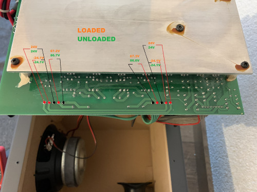
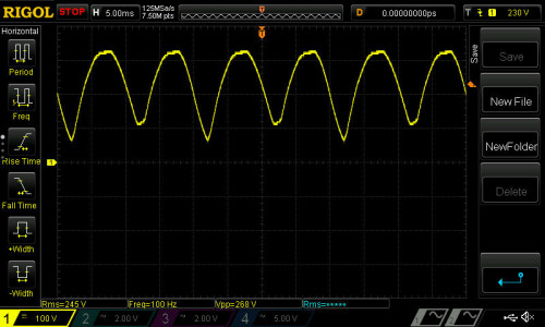
Not. I have a power grid voltage of 220VAC +/- 5% in my mill...
*
OK of course, i understand.

QUOTE(STREXNIN100 @ Jan 7 2020, 10:48 AM)
On Q2 it is more interesting than on Q3 because in this case there will be no influence of the trigger circuit D6, D7 and C54 on the waveform.
*
OK understand.

QUOTE(STREXNIN100 @ Jan 7 2020, 10:48 AM)
Understand how perfect the differential inputs (or external differential probes) of your oscilloscope are, you need to read the documentation for them. Now there is no need to measure waveforms at different points of the device at the same time - just use one channel!
Just in case for the future: please measure with a good tester the resistance between the terminals of your dif. probe. In all four possible options. If the tester shows a short circuit in at least one of the measurement options (or even a resistance of hundreds of kilo-ohms), then these dif. probe cannot simultaneously record oscillograms in different — not having a common point — device locations !! In addition, when measuring in devices with high voltages, you must make sure in the manual that your dif. probe withstand this voltage difference !!
*
My dif. probe has resistance about 10 MOhms between testing red and black plugs. 5 MOhms is the resistance between testing leads and of BNC for oscilloscope input. So it should be safe to measure couple hundreds of V.
The standard passive probes delivered with the oscilloscope has about 9 MOhms on 10x setting. So no problem too.


QUOTE(STREXNIN100 @ Jan 7 2020, 10:48 AM)
The following oscillograms are much more interesting to me now:
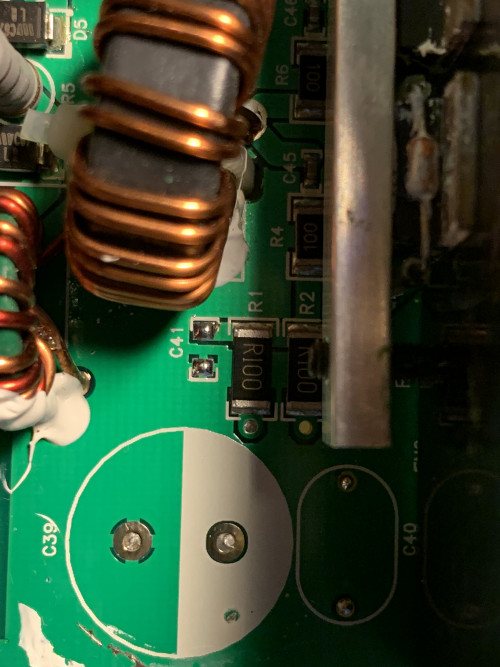
1. Between the source (S) Q2 and the anode (G) Q2.
2. Between the source (S) Q2 and the gate (G) Q2.
*
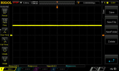
Here are the oscilograms, i was strong enough to try both channels in one screen smile.gif


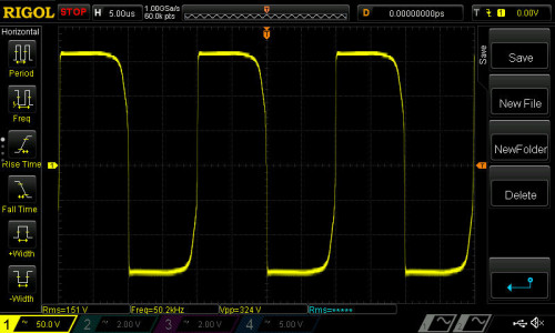
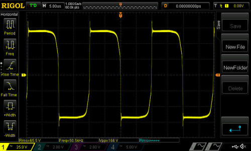
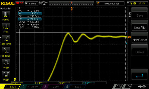
Look here:

Q2S - AD22 measured with differential probe. 500mV/div, 5us, trigger at 930mV.

user posted image

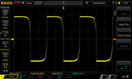
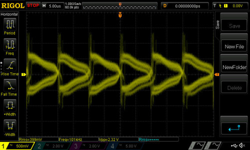
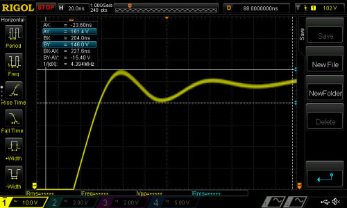
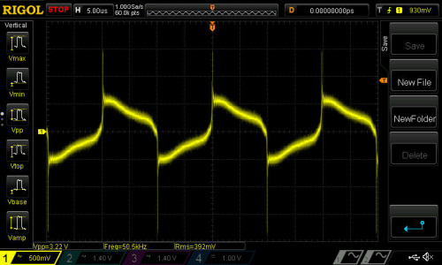
Q2S - AD22 measured with differential probe. 1,55V/div, 5us, trigger at 930mV.

user posted image

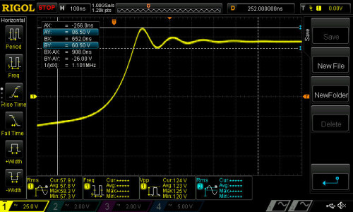
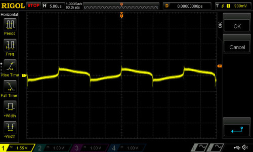
Q2S - AD22 measured with differential probe. 1,55V/div, 10us, trigger at 930mV.

user posted image

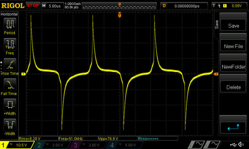
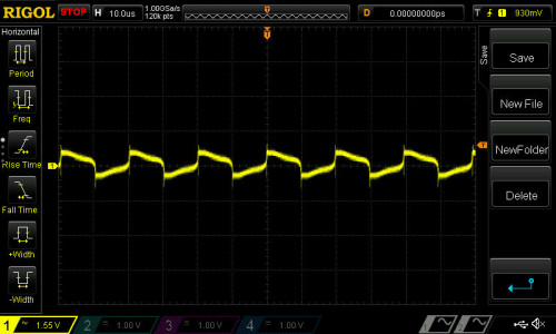
Q2S - AD22 measured with differential probe. 1,4V/div, 5us, trigger at 1.01V. Comparable oscilogram with lower one.

user posted image

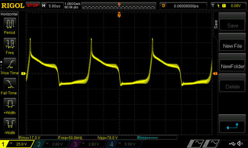
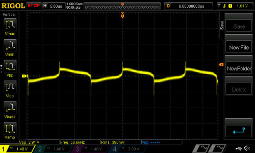
Q2S - Q2G measured with differential probe. 1,4V/div, 5us, trigger at 1.01V. Comparable oscilogram with upper one.

user posted image

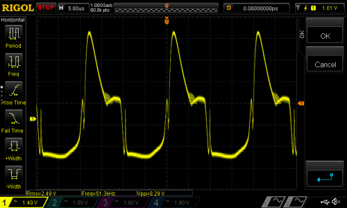
This will happend when measuring both signals (AD22 and Q2G) at once with common ground at Q2S, no matter what side is differential probe used, or diff. probe + passive probe or two passive probes.

user posted image

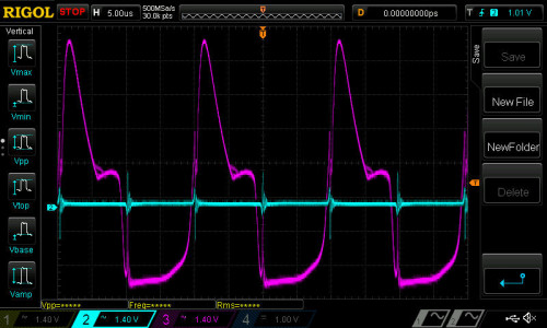
AD22 signal is ruined when try to measure it with passive probe.

user posted image

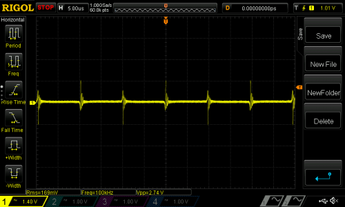
Hope this oscillograms will help you.

6 Pages < 1 2 3 4 5 > » Top
 

Change to:
| Lo-Fi Version
0.0213sec    0.29    7 queries    GZIP Disabled
Time is now: 5th December 2025 - 11:31 PM