Welcome Guest ( Log In | Register )

6 Pages « < 2 3 4 5 6 >Bottom

Outline · [ Standard ] · Linear+

PC Audio Creative GigaWorks S750 7.1 speaker repair, A short guide and info with pictures...

views
     
MichalD
post Jan 9 2020, 08:09 AM

Getting Started
**
Junior Member
104 posts

Joined: Feb 2017
QUOTE(STREXNIN100 @ Jan 8 2020, 11:05 AM)
But, perhaps, the blue waveform is not connected to the AD22 point on the board, because Q2S - Q2G and Q2S - AD22 should theoretically practically coincide in shape, and should come closer to the red graph in shape!
It seems to me that here, like the blue line in the graph above (if you look at your last message), this is not the AD22 point on the board, but the Q2S point taken by mistake! Therefore, these oscillograms look like a straight line with spurious bursts at the moment of switching the MOSFET.
*
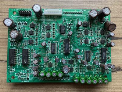
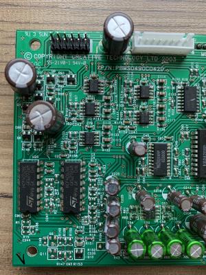
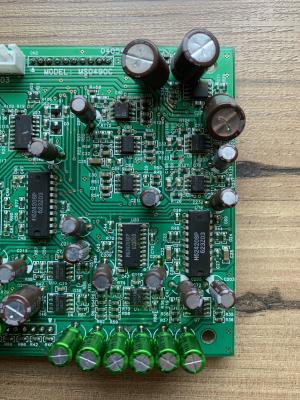
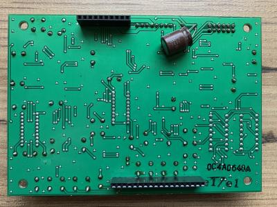
Hmmm, not sure but OK i will do re-check of the connections and post the photos during the weekend. I've soldered short leads to measuring points Q2S which is same as T1 1(4), Q2G and AD22.

QUOTE(STREXNIN100 @ Jan 8 2020, 11:05 AM)
And one more thing: it’s a little wrong that all the oscillograms were taken with the oscilloscope inputs closed (for alternating voltage). The constant component of the signal, which is not visible in this case, is very important for analyzing the correct operation of semiconductor devices!
*
Here i am not understand what are you talking about "oscilloscope inputs closed" sad.gif i am still a newbie in oscilloscope measurements and it's features, but i want to learn it all.
MichalD
post Jan 10 2020, 04:36 AM

Getting Started
**
Junior Member
104 posts

Joined: Feb 2017
QUOTE(STREXNIN100 @ Jan 9 2020, 09:15 PM)
I will try to write about it by tomorrow evening - or maybe Saturday afternoon. To write in detail, you need to be a little free.
*
OK no problem, until the weekend i am not able to make any measurements because i have all "toys" off hand.
MichalD
post Jan 11 2020, 05:54 PM

Getting Started
**
Junior Member
104 posts

Joined: Feb 2017
QUOTE(STREXNIN100 @ Jan 11 2020, 10:44 AM)
I apologize. ...
*
Unfortunately my plans was yesterday suddenly changed and i am not back at home this weekend so i have no access to maky any measurements sad.gif
MichalD
post Jan 12 2020, 12:47 AM

Getting Started
**
Junior Member
104 posts

Joined: Feb 2017
QUOTE(STREXNIN100 @ Jan 11 2020, 03:09 PM)
OK! Then I calmly finishing. ))
*
OK good luck.
MichalD
post Jan 24 2020, 04:31 AM

Getting Started
**
Junior Member
104 posts

Joined: Feb 2017
QUOTE(STREXNIN100 @ Jan 11 2020, 11:04 PM)
As a rule...
*
Hello after som time...many thanks for your detailed explanation, i need some time to absorb and understand all what you wroted smile.gif and make my own measurements to see differences between these modes.

Thank you very much. This weekend i will not be at home but next i will and check the measuring AD22 point.

MichalD
post Jan 24 2020, 06:14 AM

Getting Started
**
Junior Member
104 posts

Joined: Feb 2017
QUOTE(Bit4ever @ Jan 23 2020, 08:29 PM)
Hello everyone...
*
Hello,

good to hear that another S750 unit is brought back to life smile.gif

For the audio processing board, the broken C28 i think that will have some affect, if you are enough courageous you can try it what will it does, but not recommend, you can damage some other parts.

I can measure the value but only next weekend (not this comming, but next), i havent the board by my hand now.

I recommend you to scrape off all glue from the board, i know it is hard but not impossible, just a lot of "carefully ant work"
The glue can make conductive phantom traces after some time in next use.

Till now i scraped about 7 pcs of these smile.gif and another 3 pcs are waiting for it.

Good luck.


MichalD
post Feb 2 2020, 07:19 PM

Getting Started
**
Junior Member
104 posts

Joined: Feb 2017
QUOTE(Bit4ever @ Feb 1 2020, 03:36 PM)
I finally removed all the glue from the audio card...
*
Hello, i've desoldered the caps today and measured both for you.

C28...10,357 nF...so it will be 10nF nominal.
C85...10,732 nF...si it will be 10nF nominal too.
MichalD
post Feb 3 2020, 03:19 AM

Getting Started
**
Junior Member
104 posts

Joined: Feb 2017
QUOTE(Bit4ever @ Feb 2 2020, 04:02 PM)
What do you think about the voltage ?.
*
After checking this size of capacitors package 0.8x1.6mm it is rated for 16V so i think it will be enough.

MichalD
post Feb 7 2020, 07:47 AM

Getting Started
**
Junior Member
104 posts

Joined: Feb 2017
QUOTE(Bit4ever @ Feb 7 2020, 12:23 AM)
Thank you for your advice  thumbsup.gif ....
*
Hmmm...very hard to determine what is going on. Carefully check the audio processing board with magnifier glass for some short circuits or any other visible problems possible caused by scraping off the old glue or soldering new components. I can take detailed photo during this weekend and post here to help you.
Do you have checked the voltages of PSU?
If you disconnect audio processing board flat grey wire from woofer amp board will the buzzing sound dissapear?

What for the other AMP board it is working properly?


MichalD
post Feb 9 2020, 06:00 PM

Getting Started
**
Junior Member
104 posts

Joined: Feb 2017
QUOTE(Bit4ever @ Feb 2 2020, 03:54 PM)
hello thank you very much for your help MichalD notworthy.gif .
*
These were ceramic caps, so they are non-polarized.
MichalD
post Feb 9 2020, 06:07 PM

Getting Started
**
Junior Member
104 posts

Joined: Feb 2017
QUOTE(MichalD @ Feb 7 2020, 12:47 AM)
Hmmm...very hard to determine what is going on...
*
Here are the detailed pictures of the same board as you have but this is with new caps. Check the traces if you have accidentally scraped off some. Measure with continuity tester the resoldered input and output connectors if there are is conductivity to the board or nearest part.

Attached Image Attached Image Attached Image Attached Image

MichalD
post Feb 16 2020, 05:34 AM

Getting Started
**
Junior Member
104 posts

Joined: Feb 2017
QUOTE(kotek34 @ Feb 15 2020, 10:31 PM)
Hello to everyone...
*
Hello, will you repair it by yourself?
MichalD
post Feb 16 2020, 05:59 AM

Getting Started
**
Junior Member
104 posts

Joined: Feb 2017
QUOTE(kotek34 @ Feb 15 2020, 10:49 PM)
Hi MichalD...
*
It seems to be a stanby power section problem. Check D9, 10, 13, D26.
MichalD
post Feb 16 2020, 06:25 AM

Getting Started
**
Junior Member
104 posts

Joined: Feb 2017
Hairdryer treatment is effective for electrolytics, but only for a while. TOP243Y is suspicious, but near impossible to diagnose, just very hard to replace. Can you measure capacitance and ESR of C62 and 63?

This post has been edited by MichalD: Feb 16 2020, 06:25 AM
MichalD
post Feb 16 2020, 08:09 AM

Getting Started
**
Junior Member
104 posts

Joined: Feb 2017
Don’t think so. I think it only just works for caps.

MichalD
post Feb 16 2020, 11:41 PM

Getting Started
**
Junior Member
104 posts

Joined: Feb 2017
Hm great knowledge, i wasn't thinking that the capacitor will be totaly dead and it will cause this problem. Maybee capacitor's ESR dramatically increases and it's capacity dramaticly decreses, so there is no power for standby section at all.
Try to use Rubycon's BXW capacitor.

MichalD
post Feb 18 2020, 04:16 AM

Getting Started
**
Junior Member
104 posts

Joined: Feb 2017
First two caps loosing their capacity and ESR is increasing becuase of heat of the heatsink and therefore the standby circuit is not werking properly. Replace it for new LOW ESR one 105 °C rated for long term use. 5000 hrs or more.
Reseting is common issue on all units, you can fix this by following steps described upper in my topic posted Mar 13 2018, 10:20 PM "RELAY ISSUE (CONTROL POD RESETING) - SOLVED"


MichalD
post Feb 25 2020, 07:11 AM

Getting Started
**
Junior Member
104 posts

Joined: Feb 2017
Hello, don’t know what to measure on amp board, but they are very rare to fail besides big cap, small ceramic cap and smd cap. Try connect only 2 IC amp board and measure voltage under load where was 95V with no load. After then connect second amp board with 3 ICs an measure voltage on both amp boards under load. I think the PSU can’t deliver enough power to supply both amp boards.

MichalD
post Apr 13 2020, 02:59 PM

Getting Started
**
Junior Member
104 posts

Joined: Feb 2017
QUOTE(djozmo @ Apr 7 2020, 12:35 AM)
Hello again..
*
Hello, problem with the standby power section, can you measeure the output voltages? Check C6, C61, C8, D10, C63, D13, C62, D26. Capacitors need to be checked for capacity and ESR.
MichalD
post Apr 21 2020, 04:08 AM

Getting Started
**
Junior Member
104 posts

Joined: Feb 2017
PSU board.

6 Pages « < 2 3 4 5 6 >Top
 

Change to:
| Lo-Fi Version
0.0434sec    0.25    7 queries    GZIP Disabled
Time is now: 6th December 2025 - 08:55 AM