

when u install everything, then u show the picture....coz the whole thing is too clear until u see nothing....
AG's Gallery, everything is inside !, update: some nice fans at pg 6
AG's Gallery, everything is inside !, update: some nice fans at pg 6
|
|
 Jan 27 2006, 05:24 PM Jan 27 2006, 05:24 PM
Return to original view | Post
#41
|
 
Senior Member
4,561 posts Joined: Jan 2003 From: Penangites |
when u install everything, then u show the picture....coz the whole thing is too clear until u see nothing....
|
|
|
|
|
|
Jan 27 2006, 07:40 PM
Return to original view | Post
#42
|
|
Senior Member
4,561 posts Joined: Jan 2003 From: Penangites |
thanks man !!!
|
|
|
Mar 22 2006, 10:01 AM
Return to original view | Post
#43
|
|
Senior Member
4,561 posts Joined: Jan 2003 From: Penangites |
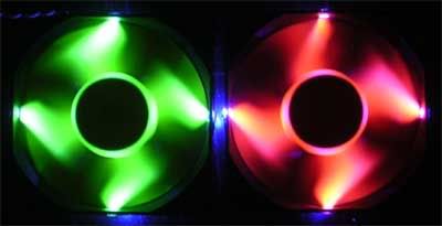
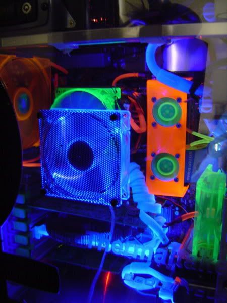
just completed this mod today, it's a 7 colour LED lighting
 with CDROM controller !!!! with CDROM controller !!!!  CCFL dudes will go crazy when they see my mod  it consists of 14 LEDs connected into 1 channel and there are 2 channels. basically, there are 6 flip switches which 3 flip switches are for 1 channel, which is RED, GREEN and BLUE channel so one flip switch controls one colour. it can give these colours : * red * green * blue * blue + green = aqua * blue + red = purple * red + green = yellow * red + green + blue = white so total is 7 colours !!!  the colours doe the switches are arranged in [ red ] - [ blue ] - [ green ] - [ red ] - [ blue ] - [ green ] just enjoy the pictures !! 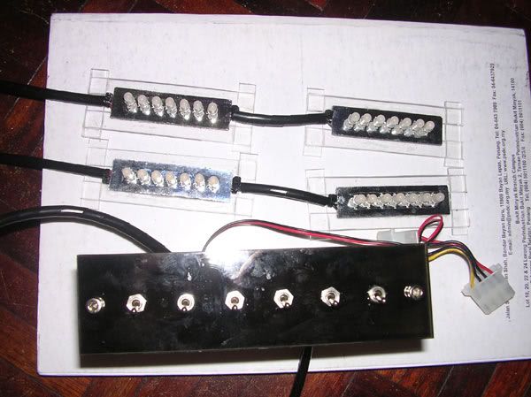 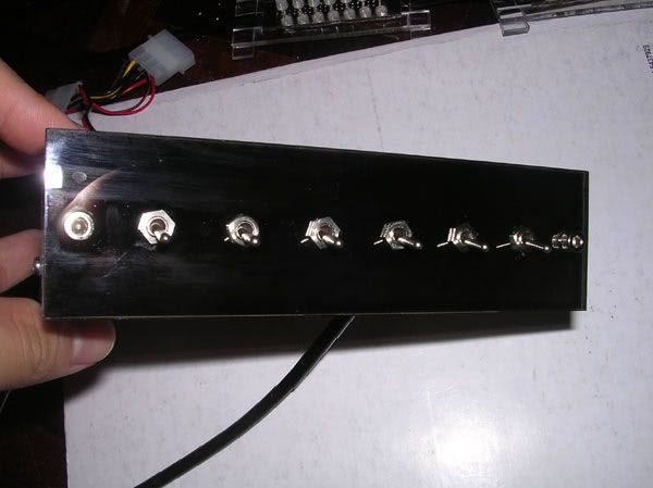 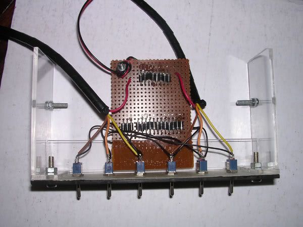 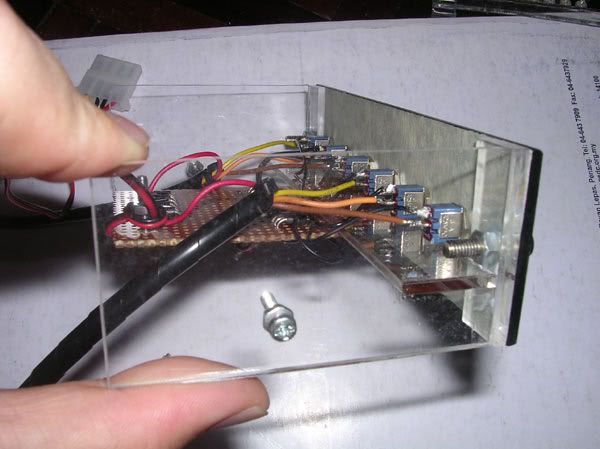 nicely positioned switches  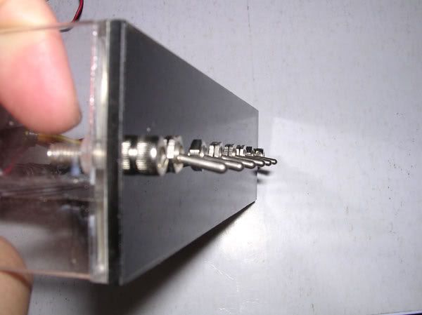 this is the LED module, i've put reflectors stickers on the PCB to reflect all the lights outwards 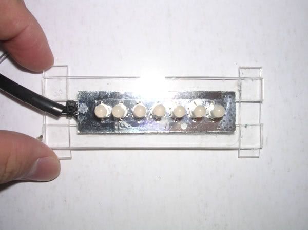 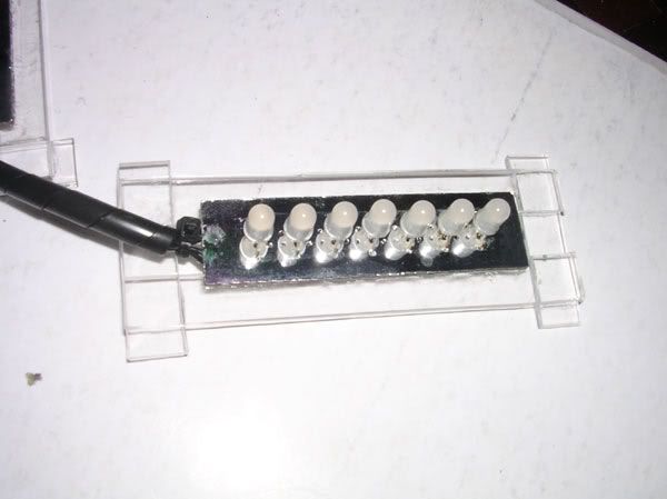 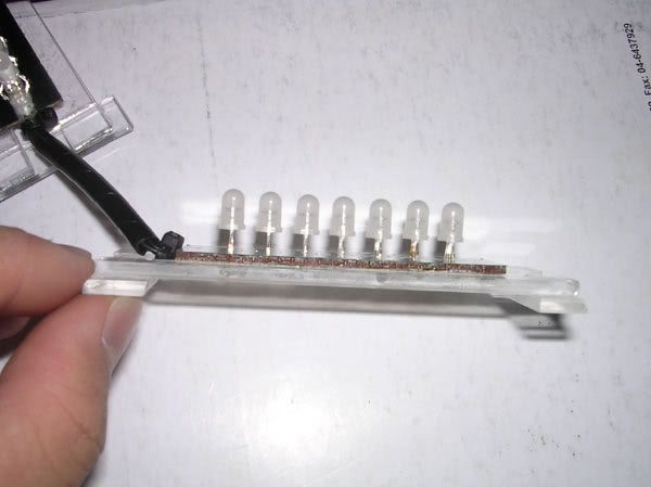 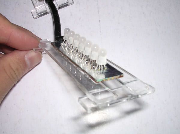 the controller bracket on my crappy casing  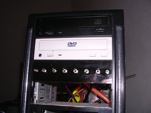 |
|
|
Mar 22 2006, 10:02 AM
Return to original view | Post
#44
|
|
Senior Member
4,561 posts Joined: Jan 2003 From: Penangites |
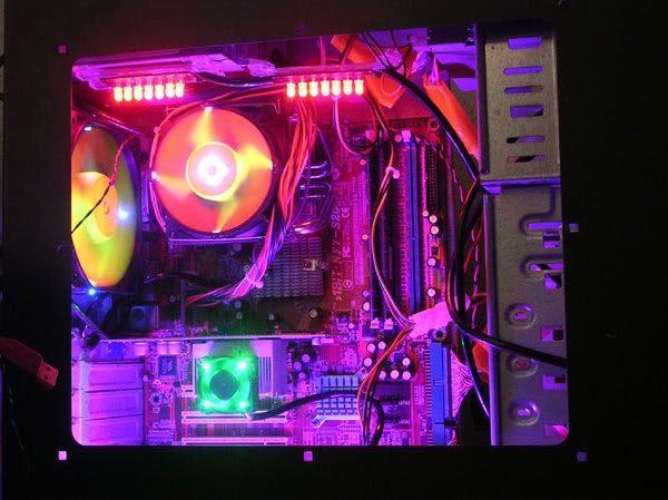
the LEDs are installed below the PSU and another channel below the casing.
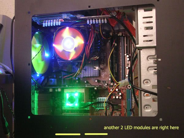  the LED colours RED 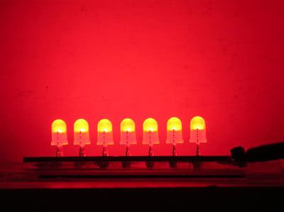 BLUE 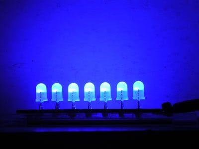 GREEN 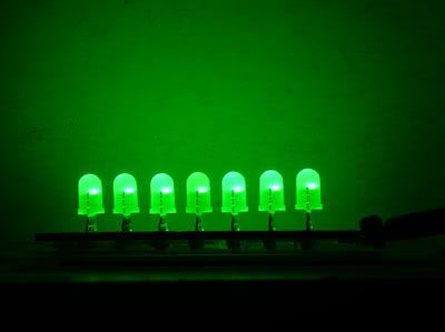 BLUE + GREEN = AQUA 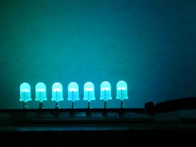 BLUE + RED = PURPLE 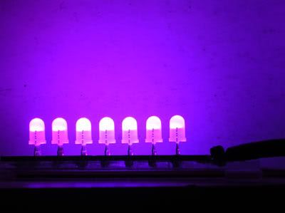 GREEN + RED = YELLOW 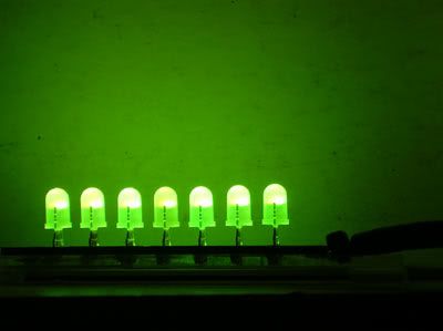 RED + GREEN + BLUE = WHITE 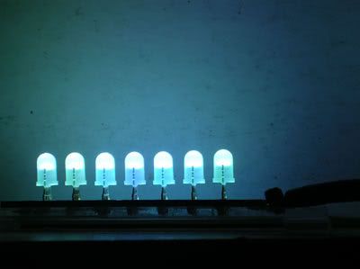 |
|
|
Mar 22 2006, 10:02 AM
Return to original view | Post
#45
|
|
Senior Member
4,561 posts Joined: Jan 2003 From: Penangites |
sorry for my lousy casing and cacing goin here and there, coz got no time to make another casing at the moment
ok, there are total of 56 combinations for the lightings, but i'll just show nice colour combinations. so just enjoy !!!! 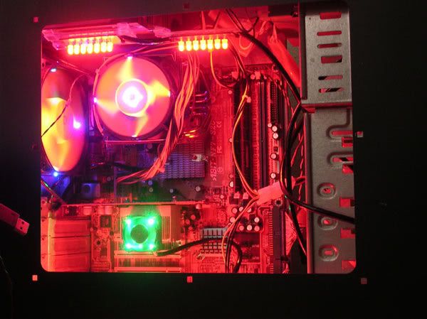 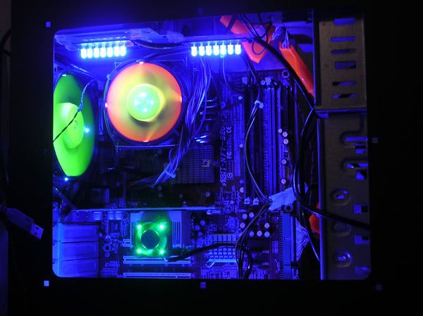 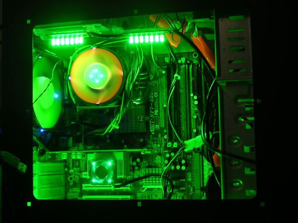 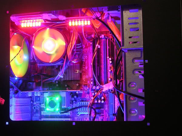 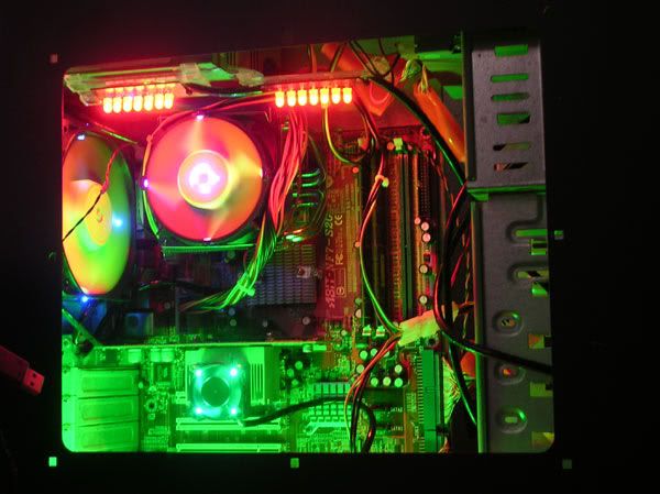 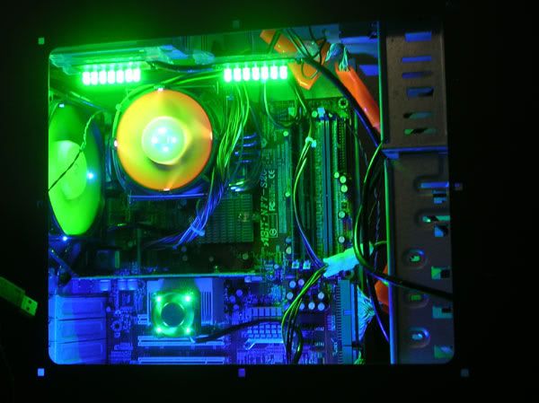 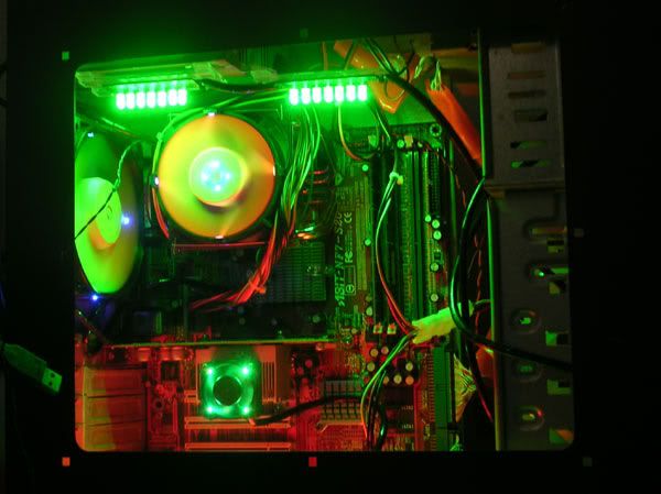 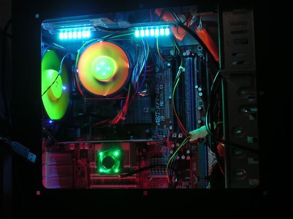 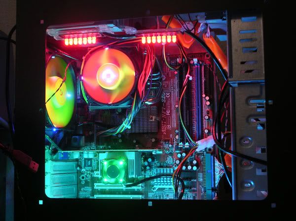 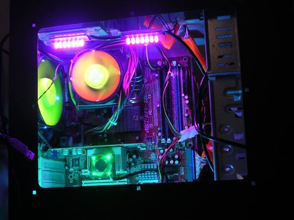 |
|
|
Mar 22 2006, 10:03 AM
Return to original view | Post
#46
|
|
Senior Member
4,561 posts Joined: Jan 2003 From: Penangites |
continue
 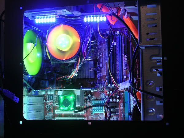 this is all for now. thanks !!  |
|
|
|
|
|
Mar 22 2006, 10:19 AM
Return to original view | Post
#47
|
|
Senior Member
4,561 posts Joined: Jan 2003 From: Penangites |
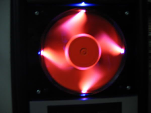
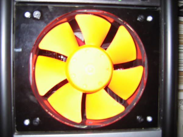
this is my latest mod, originally, this is a normal clear case fan,
so i have sprayed the blades into UV yellow, and made 4 holes and inserted 4x blue 5mm LED which i cut the oval surface and diffuse the clear epoxy. so enjoy the pics ya!! 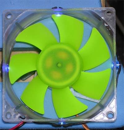 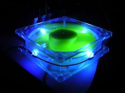 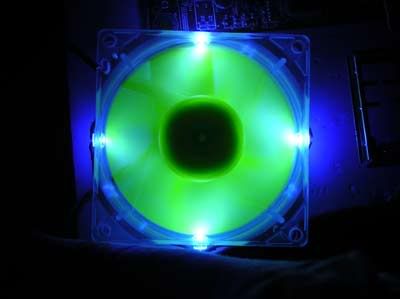 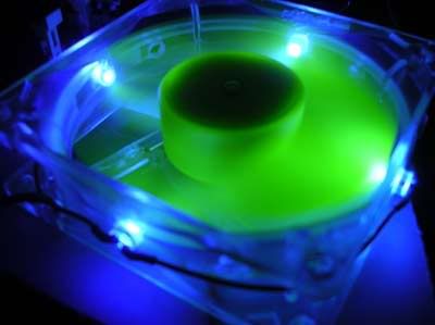 |
|
|
Mar 25 2006, 10:44 PM
Return to original view | Post
#48
|
|
Senior Member
4,561 posts Joined: Jan 2003 From: Penangites |
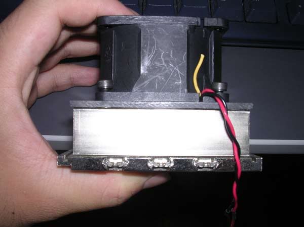 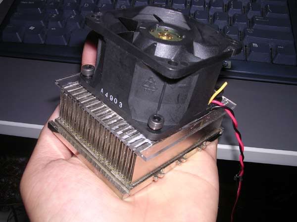 extreme compact cooling solution, for a forummer here. |
|
|
May 21 2006, 12:08 PM
Return to original view | Post
#49
|
|
Senior Member
4,561 posts Joined: Jan 2003 From: Penangites |
wanna look at my solution ??
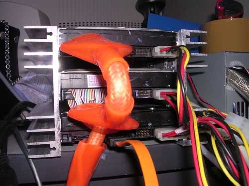 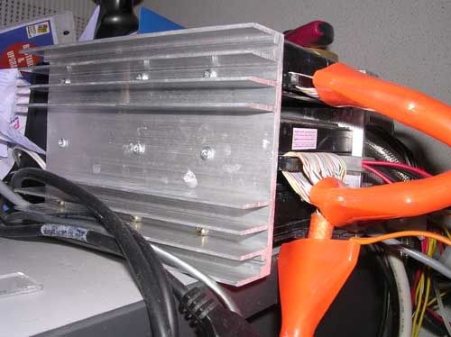 2x heatsinks sandwiched 3x HDD, i put thermal paste on the sides of the HDD. and a very low speed 92mm fan blowing in front.... it helps to lower the temperature a lot man...the heatsink is slightly warm only. |
|
|
May 24 2006, 11:24 PM
Return to original view | Post
#50
|
|
Senior Member
4,561 posts Joined: Jan 2003 From: Penangites |
naziled shots
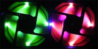  modded NMB 92mm low speed..... 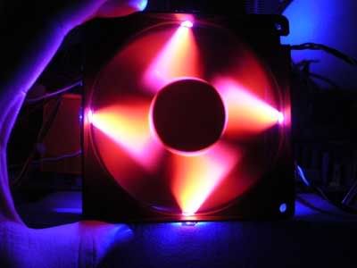 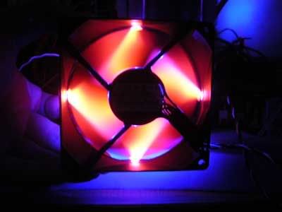 |
|
|
Aug 17 2006, 09:55 PM
Return to original view | Post
#51
|
|
Senior Member
4,561 posts Joined: Jan 2003 From: Penangites |
modded one XFX - 7600GS 256mb card
it comes stock with passive cooling, just a big area of Alu......user complaint that it will restart when it's running at full load.....so this is my solution !!! added one 92mm NMB fan (frameless) on it... reduced around 13�C from full load temperature and the card is running fine at full load 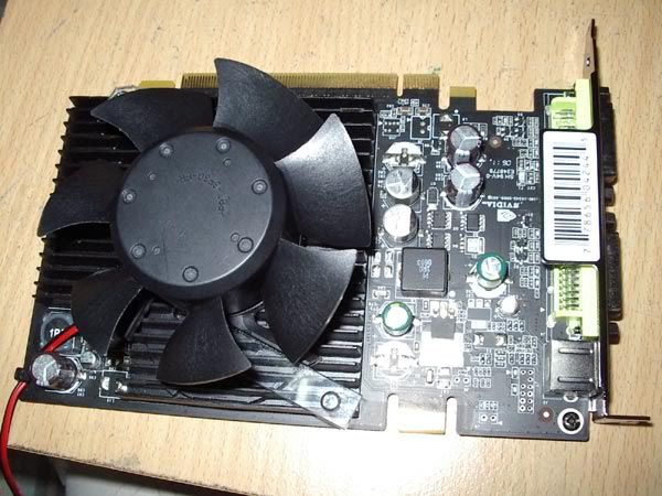 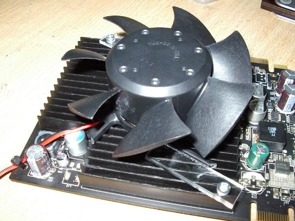 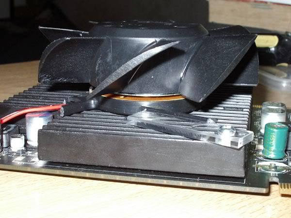 This post has been edited by AllnGap: Aug 17 2006, 09:56 PM |
|
|
Aug 28 2006, 09:36 AM
Return to original view | Post
#52
|
|
Senior Member
4,561 posts Joined: Jan 2003 From: Penangites |
this is the 120mm Naziled fitted into a acrylic faceplate at the size of 3x CDROM bay and it's placed into the front panel
    |
|
|
Aug 28 2006, 09:42 AM
Return to original view | Post
#53
|
|
Senior Member
4,561 posts Joined: Jan 2003 From: Penangites |
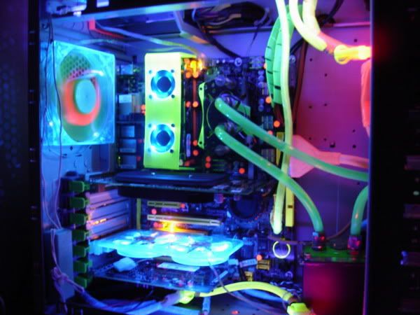
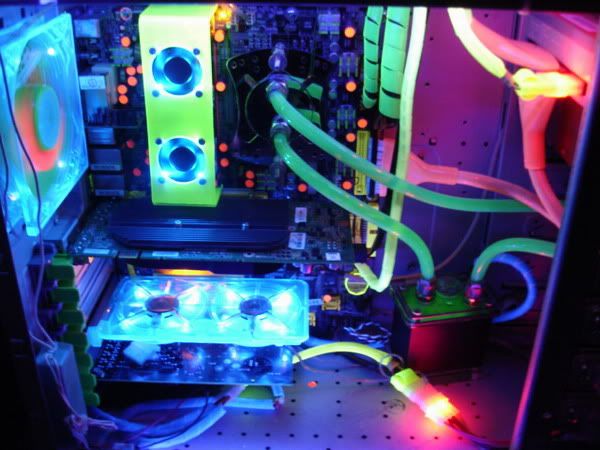
just some forummer's pics using my ram coolers......enjoy !
    |
|
|
|
|
|
Aug 28 2006, 09:57 AM
Return to original view | Post
#54
|
|
Senior Member
4,561 posts Joined: Jan 2003 From: Penangites |
okay, since i cant afford mini Imac for her, i have to make one casing that looks like mini mac
so this is what i'm going to throw into the mini casing.  - Pentium 4 1.8Ghz - Matsonic MB - 512mb value ram - lousy graphics card - DVD ROM - cap A PSU - 2 x 60mm fan - 1 x 92mm fan okay, i'm going budget on this, just nice casing, no window or whatever as long as it looks nice outside. i wouldnt want to invest on the frame, so i used the motherboard as the support for the heavy things like CDROM and HDD so basically i should stuff all these into a box measuring about 21mm(thick) x 205mm(height) x 317mm(length). 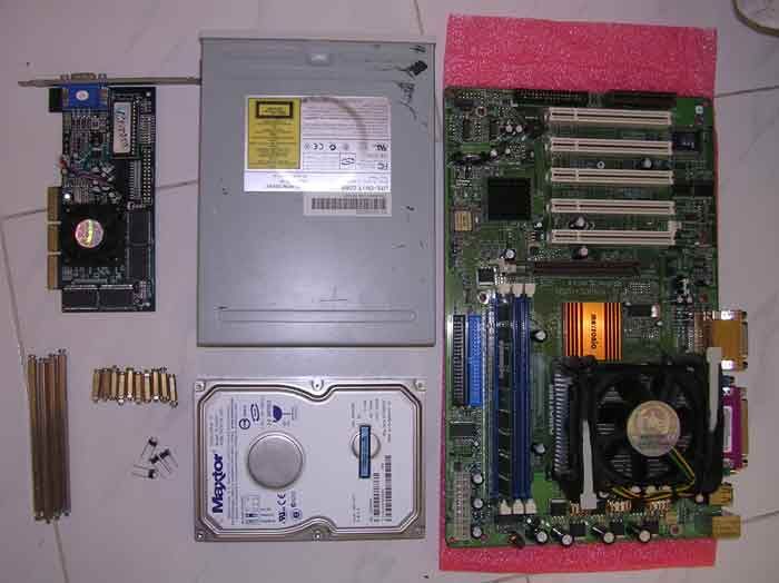 i started off with the motherboard base acrylic, drilled 7 screw holes and put in the motherboard stand. 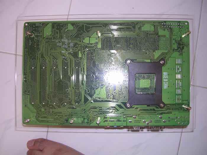 i used 4x long motherboard stands to support the base for the CDROM and HDD. those stands are really expensive but they are so useful in building workstation style design. 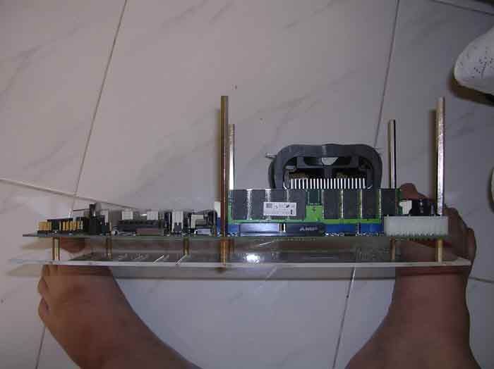 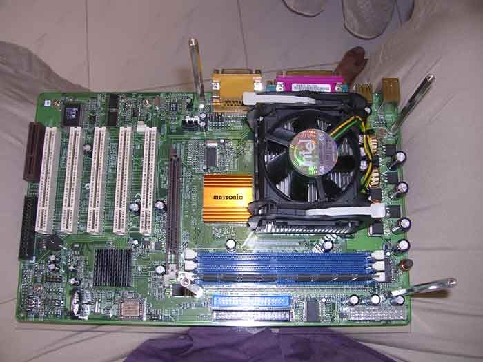 made another acrylic base for the stands 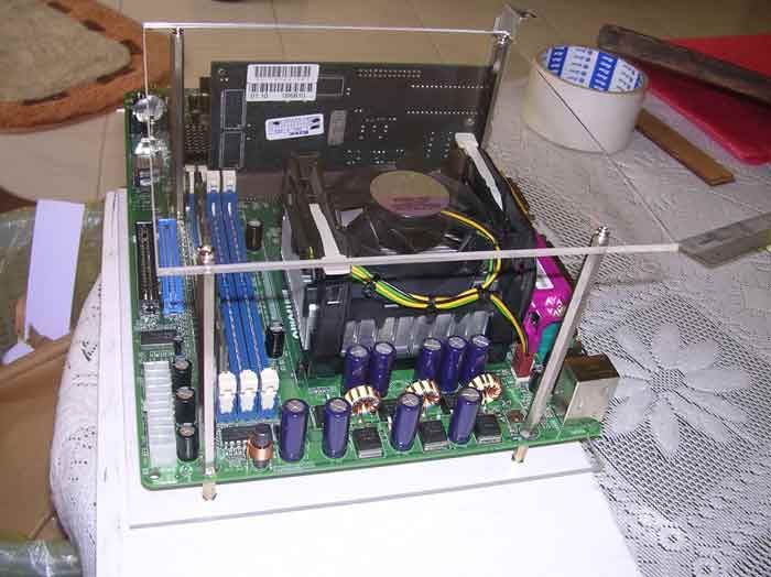 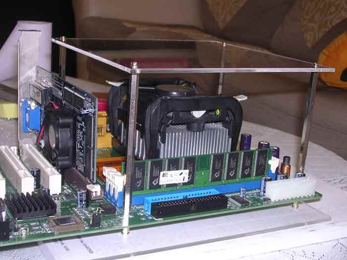 basically this arrangement is what i have in my mind, but with the PSU running naked  i'm leaving the front panel for the surprise, so i have to push the fans near the heatsink and exhaust at PSU area. 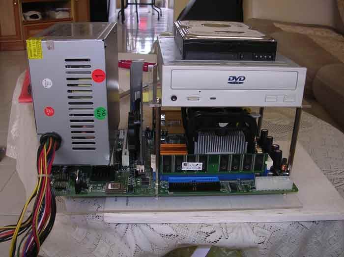 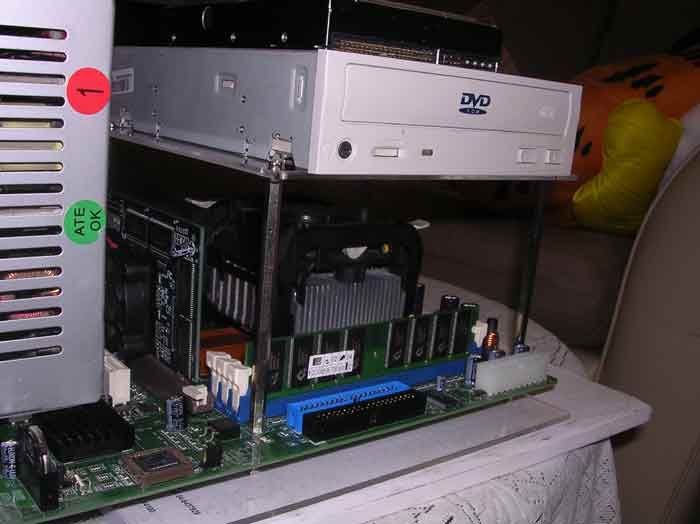 rear part of the casing 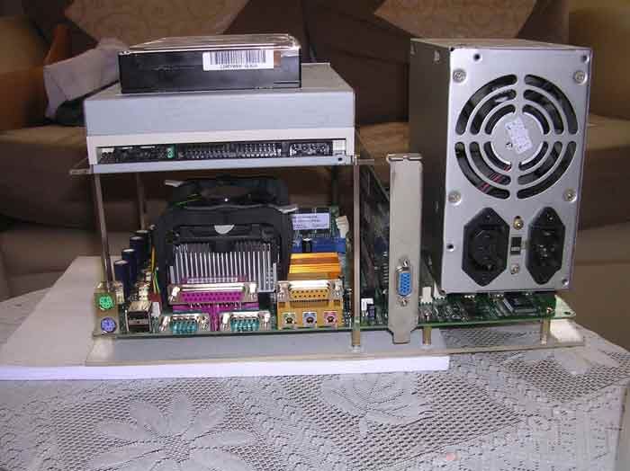 |
|
|
Aug 28 2006, 09:57 AM
Return to original view | Post
#55
|
|
Senior Member
4,561 posts Joined: Jan 2003 From: Penangites |
so i went to remove the PSU cover, chop off the fan, the power cord wires, and just a bare circuit.
as i'm using acrylic as a base, it's not grounded. hence i did some soldering to connect the 4 points. note that the 4 points are actually the Ground for the power cord 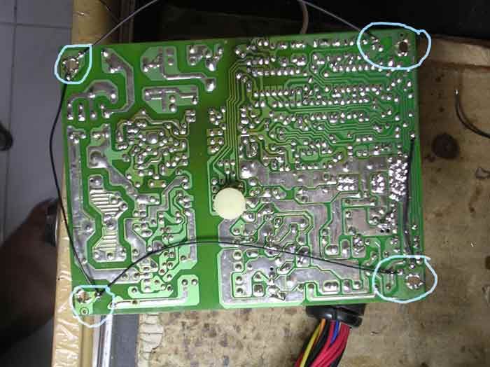 so i'll leave the PSU aside first and finish the casing before coming back to the power cord. basically this is the 2x 60mm fan holes for the intake for the CPU 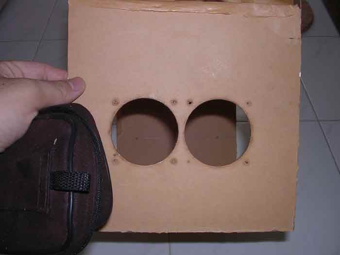 the same goes to the other side of the casing, which i made 4 holes with motherboard stand to hold the PSU. when everything is completed, i sticked them together 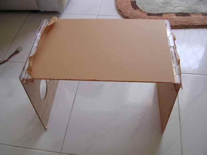 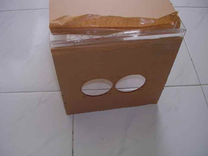 i used the triangle lining to hold the sheets 90� to each other tightly. it's really hard to use those as the adhesive could not sip nicely. i had to use syringe needle to put the adhesive to get a nice joint. had one accident there, but nvm, i'll think of a way to cover that 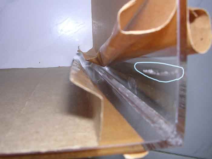 when the top and side panels are completed, it's time to finish the rear panel. i made several holes using drills, files, and hand saw, how i wished that i have a Dremel on my hand  the round hole is the 92mm fan hole while the other hole on the bottom is for the PSU power cord 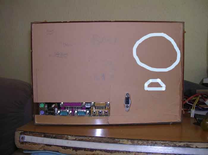 so this is how it looks like (partially) when things are being put together 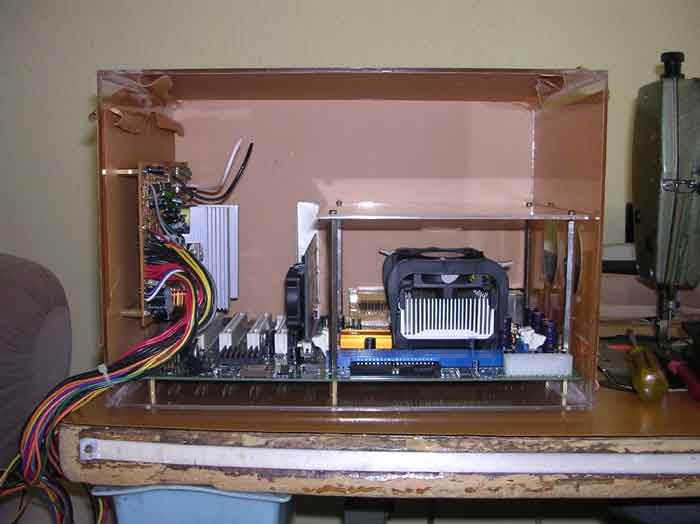 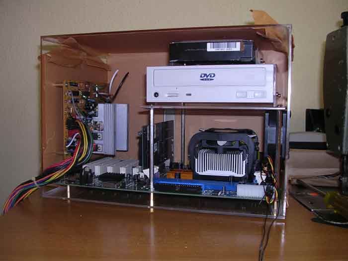 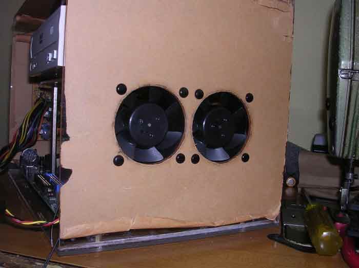 |
|
|
Aug 28 2006, 09:57 AM
Return to original view | Post
#56
|
|
Senior Member
4,561 posts Joined: Jan 2003 From: Penangites |
so i removed the motherboard from the base and then joint the whole thing.
this is how it looks without the front panel 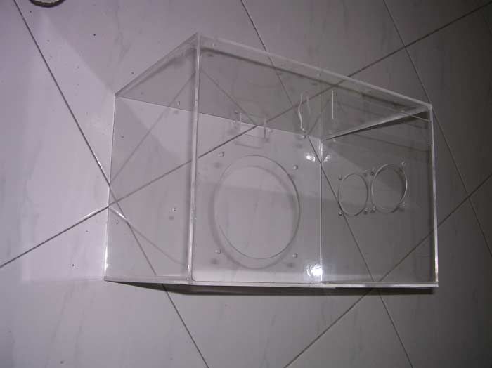 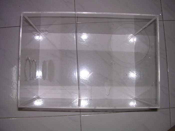 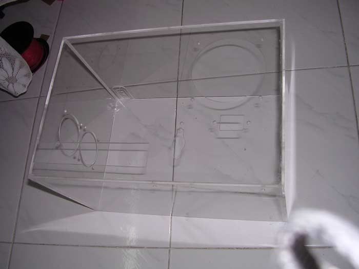 then it's spray job time !!!!! this is just the base layer coz was doing the spray job at 12.30am. note that the spray job is inside and not outside. 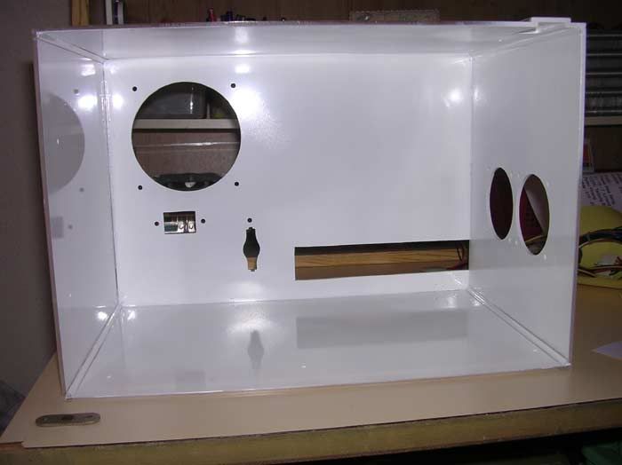 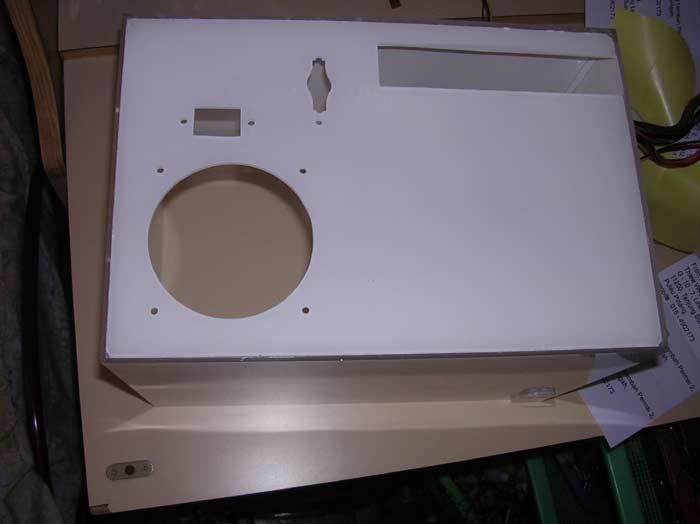 this is the left side of the casing, which is to hold the PSU 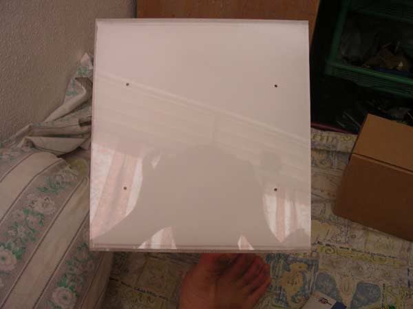 this is the rear part of the casing 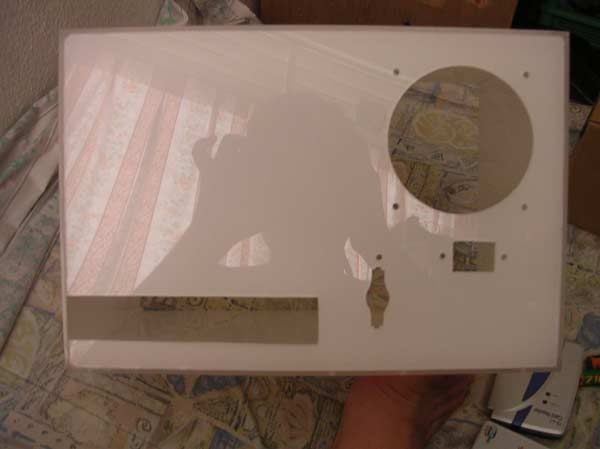 the right part of the casing, near to the CPU 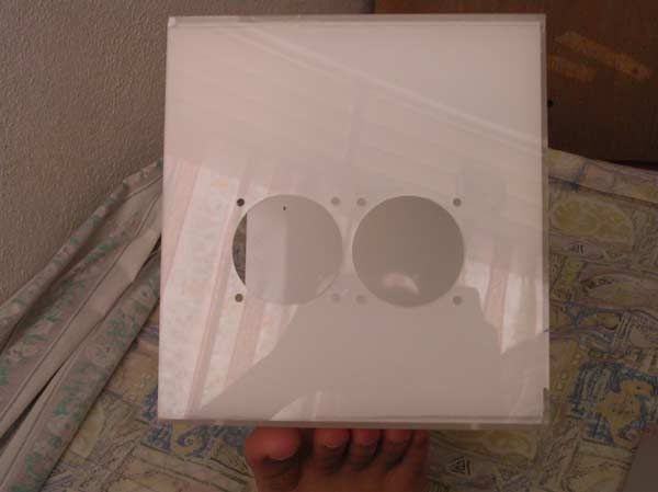 the top right corner of the PSU which had some accident just now. i cut out a corner and will put SMD LED below the 2 dots for HDD activity lighting 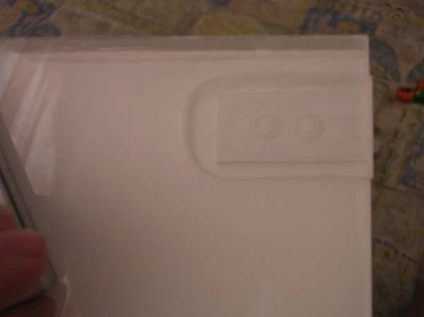 |
|
|
Aug 28 2006, 09:59 AM
Return to original view | Post
#57
|
|
Senior Member
4,561 posts Joined: Jan 2003 From: Penangites |
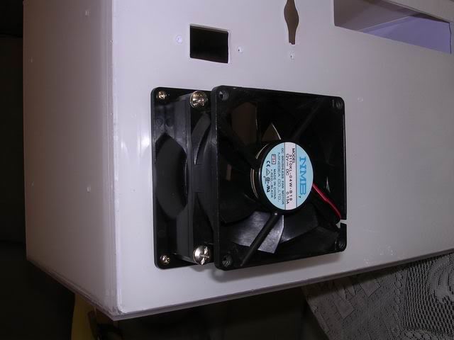
mounted a 80-92mm fan converter there, actually i thought of mounting a 92mm inside, but i dont have a slow speed one......anyway, the slow speed NMB is good enough to cool this baby down
 this is the picture of the fan from inside, and i've used A4 size white stickers to cover all surfaces to prevent any unwanted scratches during installation, and to make the paint look more solid, coz the base paint is just nice, but not solid enough. 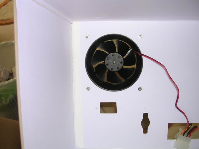 this is the front cover, by using L bracket that i fabricated to hold the thing back. but i've made some changes and i finally changed to row of L bracket instead of pcs coz it's much solid that way  i used the plastic push pins to try the fitting. the front is the surprise part !!! total clean look for it, and i've changed the original idea to put the CDROM facing the front 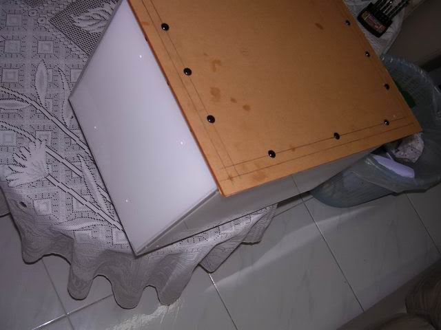 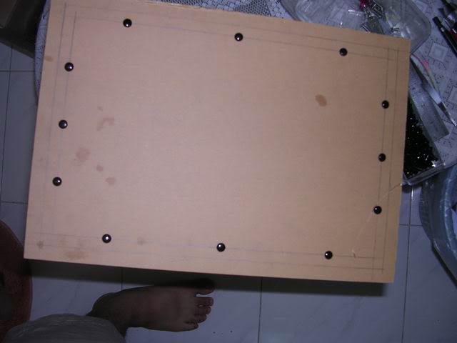 i've made an extender for to hold the CDROM and the HDD to be held from the top facing the side. 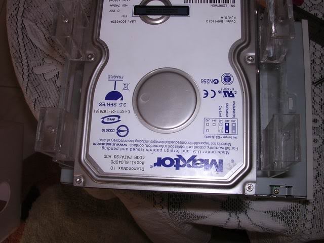 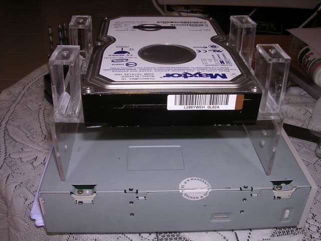 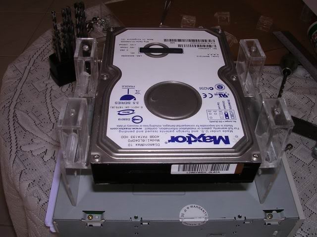 after i've mounted the CDROM, i made the markings on the position of the hole. 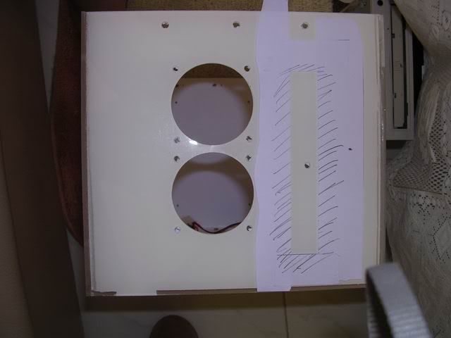 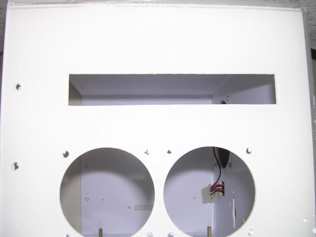 |
|
|
Aug 28 2006, 09:59 AM
Return to original view | Post
#58
|
|
Senior Member
4,561 posts Joined: Jan 2003 From: Penangites |
i've made the hole, remove the front plate of the CDROM, hook out the LED and the push button, made an 4.5mm extender so that i can use double sided tape for the new white CDROM panel with the bare CDROM tray.
the four screws are to hold the CDROM and HDD bracket 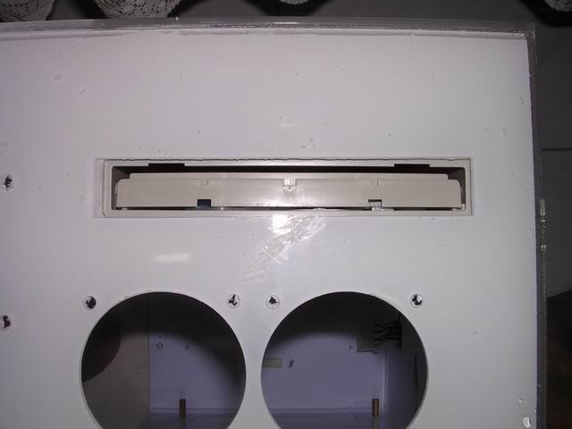 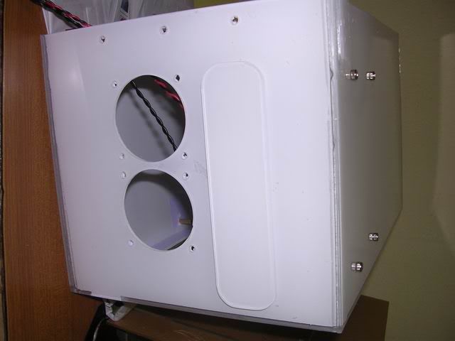 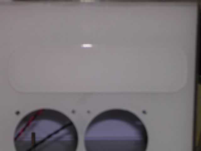 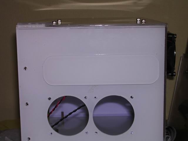 the surpise part !!! which is the front part..... took some time to get the right and cute puppies for the pics, and i had real headache arranging them nicely....  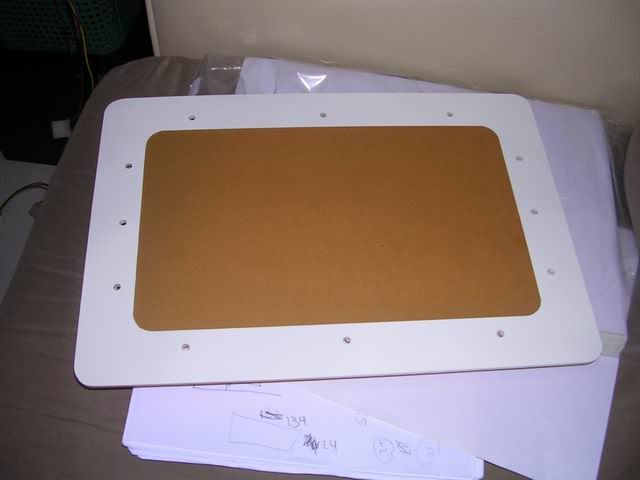  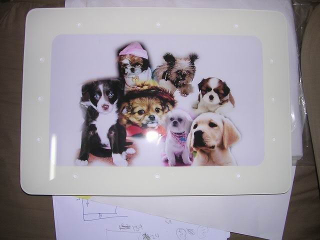 |
|
|
Aug 28 2006, 10:00 AM
Return to original view | Post
#59
|
|
Senior Member
4,561 posts Joined: Jan 2003 From: Penangites |
this is the completed product, but i'm really sorry coz i dint snapshot in detail the interior and some special features coz she needs her pc urgently.
i will take some pics and update this weekend. basically, i added leds on the 60mm fans.....i cant escape from bling bling fever and i added our picture on the top where the CDROM lies because excessive pressure from the CDROM made a slight crack on it, so i had to mark up with another layer and cover the flaw with a design. 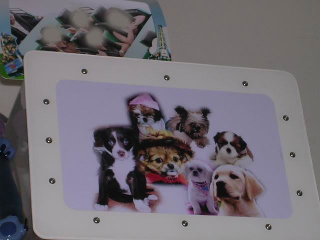 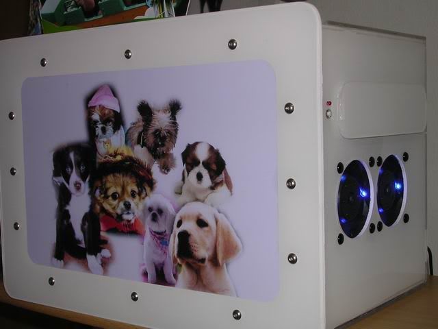 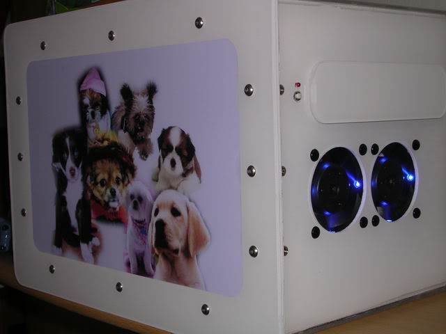 ( ianho : those are the sexy island key screws i was talking about on the front panel )i personally feel satisfied with this mod, but i would actually prefer it to be screwless coz it will give the total IMAC type of theme and the sleek look for the lady  but screw it  , coz under low budget, low space, low IQ planning style, i had to come out with this design ( microwave shape with a door in front ) , coz under low budget, low space, low IQ planning style, i had to come out with this design ( microwave shape with a door in front )but nevertheless, she loves the puppies in front more |
|
|
Aug 28 2006, 10:01 AM
Return to original view | Post
#60
|
|
Senior Member
4,561 posts Joined: Jan 2003 From: Penangites |
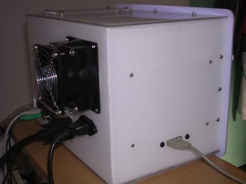 this is the back of the casing, with the 2x USB slots on the left side of the casing, the 4 screws are for the PSU PCB mounts screws. 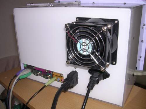 another rear shot, used 80-92mm converter, 80mm NMB low speed fan as exhaust.  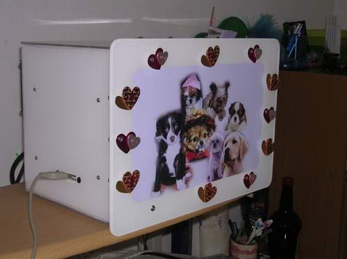 we went to the lifestyle shop and found something nice to cover those rounded allan key screw heads, it's love shape with double sided tape behind.  so she did this mod herself 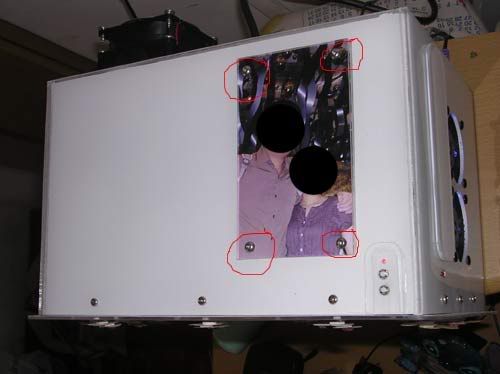 this shot is taken from the top. the 4x screws are used to hold the bracket for the CDROM and the HDD...... as i said earlier, due to the weight and the pressure from the screws, the acrylic had a small crack and i had to use this way to cover the damage. thus i stick on layer on the casing, and then used another layer to cover the pics..... the corner with the LED and 2x switches is actually the HDD activity light, ON/OFF switch and RESET 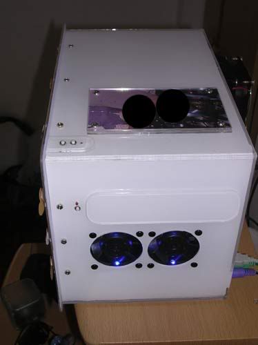 this shot is taken from the right of the casing with flash...... 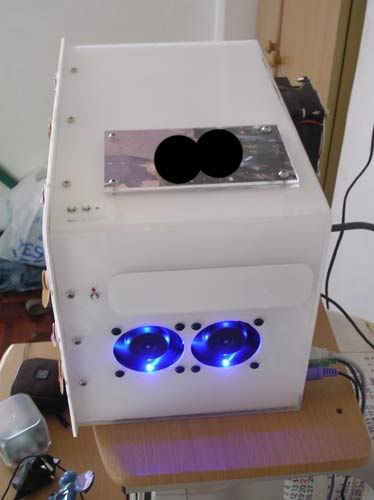 this shot is taken from the right of the casing without flash......  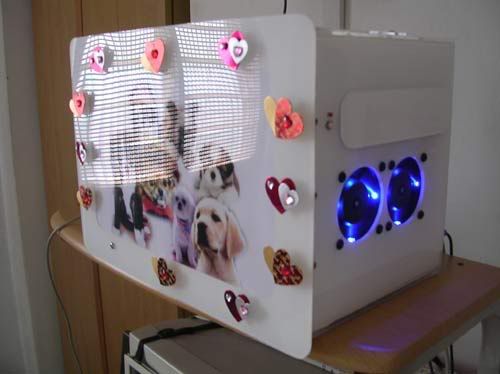 basically, this is how it looks like after some " modding " done by my gf......kinda pimpin' now 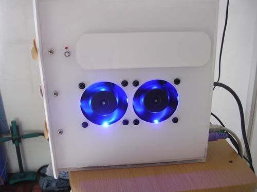 as u can see the dual 60mm fan setup with LEDs in it and the CDROM bay which i stealthed it with a white acrylic faceplate |
| Change to: |  0.0224sec 0.0224sec
 0.81 0.81
 7 queries 7 queries
 GZIP Disabled GZIP Disabled
Time is now: 21st December 2025 - 11:24 AM |
 Quote
Quote