Welcome Guest ( Log In | Register )

16 Pages  1 2 3 > » Bottom

Outline · [ Standard ] · Linear+

 Smart Home, Let's discuss

views
     
lucaswjk
post May 30 2018, 04:49 PM

~im coming~
*******
Senior Member
3,816 posts

Joined: May 2008
From: The other side...
hi all, im trying to mod my autogate to smart.
thanx to ozak, i currently change my options from sonoff sv to inching

but currently i found another problem, my autogate board might not have DC12V.

i have create a wiring diagram and post some pix of the board here
DIY/Mod AutoGate to Smart, sonoff projec

so what is my options?

ps: i dont hv e&e skill sweat.gif

lucaswjk
post May 30 2018, 09:43 PM

~im coming~
*******
Senior Member
3,816 posts

Joined: May 2008
From: The other side...
QUOTE(Kiding @ May 30 2018, 09:09 PM)
I saw a yellow square box looks like 12V battery, if it is, then you got DC12V source.
*
i think tat is transformer...

but my other option is the follow the power used by the RF module.
someone said normally it is 5v
but i didnt see any 5v indicator on the board
lucaswjk
post May 30 2018, 09:53 PM

~im coming~
*******
Senior Member
3,816 posts

Joined: May 2008
From: The other side...
QUOTE(idoblu @ May 30 2018, 09:48 PM)
I saw 12v there
*
u mean the one wrote
24v12v0v12v24v

i believe tat is AC power being stepped down
lucaswjk
post May 30 2018, 10:07 PM

~im coming~
*******
Senior Member
3,816 posts

Joined: May 2008
From: The other side...
QUOTE(idoblu @ May 30 2018, 10:03 PM)
I believe itโ€™s DC. Can see the rectifier beside the transformer.
The IC chip there needs DC to run a small well
This one must ask ozak to confirm.
*
it wrote Trans Out at the bottom...

i hope im wrong and it is DC
lucaswjk
post May 30 2018, 10:18 PM

~im coming~
*******
Senior Member
3,816 posts

Joined: May 2008
From: The other side...
QUOTE(Kiding @ May 30 2018, 10:11 PM)
If you know how to use voltage meter, switch it to DC, red color probe goes to + and black color probe goes to "-" or "ground", then you will know it is DC 12V or not
*
will buy voltage meter this weekend
donno how to use...
---

QUOTE(idoblu @ May 30 2018, 10:12 PM)
Your autogate already got a remote right? Why need the sonoff for? If no internet you canโ€™t open your gate
*
my remote sometime not working, not sensitive.
i believe the frequency need to re-tune.

most importantly not enuf remote control.
and all family member hv phone... tat solve it
lucaswjk
post May 30 2018, 10:31 PM

~im coming~
*******
Senior Member
3,816 posts

Joined: May 2008
From: The other side...
QUOTE(Kiding @ May 30 2018, 10:27 PM)
Can remote open/close autogate from anywhere  brows.gif

If the smart house apps has geo-fence feature, autogate can automatically open when you are returning to your home!  no need to press any key! rclxms.gif
*
haha not bad idea, can program with gps tracking.

but will be dangerous if hit ppl or neighbor car...
lucaswjk
post May 30 2018, 10:39 PM

~im coming~
*******
Senior Member
3,816 posts

Joined: May 2008
From: The other side...
this is jus a fun project,
if this works... mayb can do more in the future
โœŒ
lucaswjk
post May 31 2018, 01:32 PM

~im coming~
*******
Senior Member
3,816 posts

Joined: May 2008
From: The other side...
ozak the diagram ur draw is accurate, and no backup battery

Zot from the rectifier pix, i think the board hv DC... but the INPUT/OUTPUT operation all in AC
when i buy the voltage meter, then i will able to test whether the motor is AC Motor
ps: or can i just test with Test Pen??

i redraw this to include more details
Attached Image

Another thing is I notice inside RF Module have 2 small black box written as
TIANBO HJR-4102E-D-09V
3A 120VAC
3A 24VDC
--> RF is also AC box

This post has been edited by lucaswjk: May 31 2018, 01:40 PM
lucaswjk
post May 31 2018, 02:30 PM

~im coming~
*******
Senior Member
3,816 posts

Joined: May 2008
From: The other side...
1. is there any other way i can leech power from the board or RF module (from COM and NO interface)?
and what is the COM NO interface power rating?

2. using sonoff basic and reprogram it to self locking?... because of AC power...

3. else use more comprehensive solutions, as recommended by Snoy
using RF to control RF...
lucaswjk
post May 31 2018, 02:35 PM

~im coming~
*******
Senior Member
3,816 posts

Joined: May 2008
From: The other side...
QUOTE(ozak @ May 31 2018, 02:27 PM)
Can you double confirm this supply is AC or DC ?

user posted image

Can you open the remote black box and take the pic behind and front internal ?

Very rare an external remote receiver running on AC24. Mostly either AC240 or DC5/12/24.
*
i confirm the board is written AC24 (i too suspect it should be AC240) and

another confirmation is... inside RF Module (black box)
there is a 2 small box written
TIANBO HJR-4102E-D-09VTIANBO HJR-4102E-D-09V
3A 120VAC3A 120VAC
3A 120VAC3A 120VAC

is the item is converting AC to DC?
lucaswjk
post May 31 2018, 02:38 PM

~im coming~
*******
Senior Member
3,816 posts

Joined: May 2008
From: The other side...
QUOTE(ozak @ May 31 2018, 02:35 PM)
You need to provide us more information.
*
Attached Image
this pix enuf?
i can to get the back pix tonight

need me to peel off the warranty sticker???

This post has been edited by lucaswjk: May 31 2018, 02:41 PM
lucaswjk
post May 31 2018, 02:47 PM

~im coming~
*******
Senior Member
3,816 posts

Joined: May 2008
From: The other side...
QUOTE(Zot @ May 31 2018, 02:43 PM)
That black boxes are relays. Looks like the relay coil is using 9V. The contact can handle 120V at 3A
*
oic...
then i believe this relay coil is the one switching the COM-NO

... no wonder it have 2

correction on relay
TIANBO HJR-4102E-D-09VTIANBO HJR-4102E-D-09V
3A 120VAC3A 120VAC
3A 24VDC3A 24VDC

This post has been edited by lucaswjk: May 31 2018, 02:52 PM
lucaswjk
post May 31 2018, 02:59 PM

~im coming~
*******
Senior Member
3,816 posts

Joined: May 2008
From: The other side...
QUOTE(ozak @ May 31 2018, 02:56 PM)
No need peel off the sticker.

I need behind the circuit jalan. Cause I want to know is the relay is isolated or supply connected.
*
ok will repost tonight... after work

i hope it wont rain today.. ๐Ÿค

This post has been edited by lucaswjk: May 31 2018, 03:09 PM
lucaswjk
post May 31 2018, 03:25 PM

~im coming~
*******
Senior Member
3,816 posts

Joined: May 2008
From: The other side...
haha need to solder to get power from (rectifier) pcba...
i gv up...
lucaswjk
post May 31 2018, 10:33 PM

~im coming~
*******
Senior Member
3,816 posts

Joined: May 2008
From: The other side...
QUOTE(lucaswjk @ May 31 2018, 02:59 PM)
ok will repost tonight... after work

i hope it wont rain today.. ๐Ÿค
*
as expected raining... haiz
and it is still raining at my place here
lucaswjk
post Jun 1 2018, 03:04 PM

~im coming~
*******
Senior Member
3,816 posts

Joined: May 2008
From: The other side...
sorry for the late reply,
here the back pic of rf module

Attached Image

i hv oso identified the rectifire "leg", the leg quite long.

RET 50A/800V
-AC
AC+
lucaswjk
post Jun 1 2018, 03:10 PM

~im coming~
*******
Senior Member
3,816 posts

Joined: May 2008
From: The other side...
QUOTE(henryj8 @ Jun 1 2018, 01:50 PM)
wow...so complicated to control the autogate from Ewelink App. I dont think you get the correct component to integrate. Just my 2 cents
*
sonoff is good coz it able to power the electrical components directly via the power source.

hahaha actually i agreed with u.
but i hv learned alot, lucky i ask first before i make the purchase.
thank to the helpful community here.
lucaswjk
post Jun 1 2018, 03:35 PM

~im coming~
*******
Senior Member
3,816 posts

Joined: May 2008
From: The other side...
QUOTE(Zot @ Jun 1 2018, 03:26 PM)
It looks like that this RF module board get DC power from the main board through the Black and Red wire. That big capacitor 1000uF 50V is just to stabilize the incoming DC. The voltage then is regulated to 9Vdc to power the module through the voltage regulator RG2 at the tip of the capacitor.

The RF module receives the signal from remote to close contacts on both relays. One for right motor and the other for left motor. The relays act just like switches.

The relays on the main boards is switching the power on the motors.
*
will sonoff inching still workable?
coz it hv power rating 5v/12v only...

and what is the output power rating for the NO-COM? 9v??
lucaswjk
post Jun 1 2018, 03:51 PM

~im coming~
*******
Senior Member
3,816 posts

Joined: May 2008
From: The other side...
QUOTE(Zot @ Jun 1 2018, 03:48 PM)
The 9V is the coil voltage to open and close the relay.

Relay notation usually like this:
COM > Common
NO > Normally Open
NC > Normally Closed

It is like 1P2T (1 Pole 2 Throw) switch

So, when the coil is power, the COM will connect to NO. Otherwise, COM will connect to NC.

Never look at Sonoff product spec. Maybe others knew better. Which Sonoff model are you talking about? I can search for it.
*
this one
1 Channel Inching /self-locking WiFi Wireless Switch 5V 12V
lucaswjk
post Jun 1 2018, 04:12 PM

~im coming~
*******
Senior Member
3,816 posts

Joined: May 2008
From: The other side...
QUOTE(Zot @ Jun 1 2018, 04:03 PM)
I see that Sonoff has two different version, the 5V and 12V.

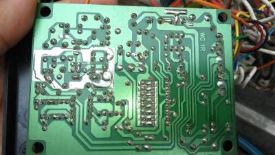
You need to know what is the voltage that comes from the Red & Black wire to the RF module. My guess it probably is 12V.
*
i think it can operate on 2 different power source,
or it hv jumper to switch the operation mode

QUOTE(ozak @ Jun 1 2018, 04:04 PM)
The RF is supply by the board AC24. RF itself have the rec to convert to DC.

1 relay is control side open ?  and 1 is control fully open ?

What is side open ?
*
if not mistaken
side open is swing single gate,
full open is swing both gate...

ok will try to short it tonight, hopefully no rain again ๐Ÿ˜…

16 Pages  1 2 3 > » Top
 

Change to:
| Lo-Fi Version
0.3545sec    0.81    7 queries    GZIP Disabled
Time is now: 27th November 2025 - 02:37 PM