

 May 28 2018, 05:35 PM, updated 8y ago

Im at planning stage to mod my autogate with sonoff sv.
Before i proceed, need some expert here to correct me...
Please note, I do not have E&E skill...
Im doing this for fun...
Gate: C S Swing Gate Auto
Model: CS 5116
Full Set, I believe the black box is RF module

Board Picture

It have the following interface
Note: I do not have the manual for this gate, haiz... this why Im drawing this
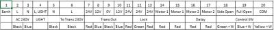
Full Diagram

Sonoff SV

I believe the RF module is using DC power, that why I choose Sonoff SV for this project.
The part i planned to mod-in is (18), (19), and (20) interface.
1. Based on the diagram, it did not show the DC voltage for RF module.
What is the general power for RF module 5V? 12V? 24V?
btw What does COM interface mean?
2. The trigger point is based on pulse button (single press) to open and close.
Ewelink able to set 1second timer to simulate the on/off pulse, this will work rite?
3. I know sonoff sv is single channel, but we can mod it to hv 2 channel rite?
1st channel = open single gate
2nd channel = open both gate
4. Do I need a relay for the pulse switch? if yes how big?
note: sonoff hv build-in relay...
5. Ok here is another tricky part, can I have close/open gate status?
sacrificed 2nd channel, mod it to status monitoring... ??
This post has been edited by lucaswjk: May 31 2018, 01:25 PM
 Quote
Quote

 0.0165sec
 0.38
0.38
 6 queries
 GZIP Disabled