


Close up of the USB port, tested stronk enuff to withstand the plug in/out process

Nice didn't interfere with the USB 3.0

Going plug crazy!!!!

Project Final-Mod (Ex-Project Anti-Establisment), Start Jan 2011, End Jan 2016.... tbc..
|
|
 Oct 19 2014, 12:16 AM Oct 19 2014, 12:16 AM
Return to original view | Post
#21
|
 
Senior Member
3,902 posts Joined: Jul 2005 From: Sin Lor, B'worth,Pg. |
Then there's the simple mod for the USB
Close up of the USB port, tested stronk enuff to withstand the plug in/out process Nice didn't interfere with the USB 3.0 Going plug crazy!!!! |
|
|
|
|
|
Oct 19 2014, 09:25 PM
Return to original view | Post
#22
|
|
Senior Member
3,902 posts Joined: Jul 2005 From: Sin Lor, B'worth,Pg. |
A simple update for a simple Sunday
back panel reinforcement   Then more acrylic cutting  OMG need to go back to milling some more..  What is it for? will give more update tomorrow  |
|
|
Oct 23 2014, 02:29 PM
Return to original view | Post
#23
|
|
Senior Member
3,902 posts Joined: Jul 2005 From: Sin Lor, B'worth,Pg. |
Finally got the Acrylics cut ans shaved down
 1st edge done by myself easy-peasy then this happened  Left the other 3 bars to the pros,  Nice and straight  Yesterday have some free time so brought out the heater for bending acrylics  After some toiling and test, nice...     tbc |
|
|
Oct 23 2014, 02:47 PM
Return to original view | Post
#24
|
|
Senior Member
3,902 posts Joined: Jul 2005 From: Sin Lor, B'worth,Pg. |
Add the top in...
  Later on done some modification to make it more streamline  these panel will be painted black to cover up the back panel housing the wirings at the mean time, some reminiscing Some old drawings, on a stack of paper been crush over 2 years time:    now transfered to new filing   Basically the concept is still there but it is cleaned up to simplified to realistically do-able Stuff to do: 1. 2. 3. 4. Clean all cutting edges - SEMI-DONE For the week ends??? ---4a. Prepare acrylic for painting... wait ---4b. HDD cage screw alignment SATISFIED!!! ---4c. Bottom Fan Holes, Acquire fan filters ... 1st half done, 2nd half... eehh ... ---4d. ---4e. U-Channel edge trim 5. Buy New Acrylic for side panel - Search search search!!!! 6. Cut side panel Acrylic -  7. Cut front panel - OII!!! NO SEE ABOVE??? FIND THE BLARDY ACRYLIC FIRST LAHHH!!!! Then we talk.  8. .. 9. . 10. Paint or..or..or... hear me out... what if....Powder Coat?.... sheet... $$$  $$$ $$$This post has been edited by mcchin: Oct 23 2014, 04:04 PM |
|
|
Nov 8 2014, 01:52 AM
Return to original view | Post
#25
|
|
Senior Member
3,902 posts Joined: Jul 2005 From: Sin Lor, B'worth,Pg. |
after a silent week
I am BACK!!! if anyone still reading this worklog  let get straight to the dirty grime The thin acrylic need some cleaning  close up  Goddammnit, this stuff is hard after scrapping with a aluminum bar The goop is clean off by something not expected 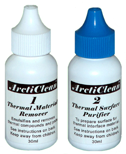 The thermal compound cleaning solvent is very good in dissolving the protective layer melted glue Finished products   so the product is cleaned Not shiny, its okay, since I intend to paint over these part if not, Acrylic is easily buffed back to shininess (not a crack, but some lint )Then on the same day received this:  can't do anything in the weekdays since have to travel then got some time off on Thursday and got down to cutting, with just an angle grinder  YEAH GOING FOR THE Lockheed F-117 Nighthawk/Northrop Grumman B-2 Spirit CASE LOOK!!!  eerrr.... no, it is just the left overs this is the parts i cut out  the smaller piece is to replace the HDD cage plates the long pieces is the front, the square is the side panel A comparison between the old acrylic (~2.7mm) and the new one (~8mm)  So what will be needed to be done in the coming weeks 1. Clean the edge of the cut piece - Tommorow (or today, saturday) 2. Starts some base coat painting, if possible 3. Get some magnet-screws drilling done 4. PAINT!! PAINT!!! PAINT!!!!! 5. Then install the parts   |
|
|
Nov 26 2014, 09:39 AM
Return to original view | Post
#26
|
|
Senior Member
3,902 posts Joined: Jul 2005 From: Sin Lor, B'worth,Pg. |
The closer it gets the harder for me, as always...
the fire is just not there.... Well I skip a lot of the milling/drilling process pictures here's the side panel attached, paper yet to be removed  The other side  as you see, vertically on the left side   I got greedy and try to maximised the window size. Forgot to take account the frame thickness and in the end the big screw would not fit in, unless i cut away the frame (because the side panel need to slide in) as you can see the pencil marks in the end settle for a small replacement holding screw inside and the 3 big screw will be just ornament stuck in for sake of filling up the hole Some small mods original  went back milling to open up the middle pocket to bigger size to facilitate easier screw removal  also seen in the picture above (forgot to take individual pic) is the HDD cage assemble with the new 8mm plates on both end Now the HDD cage is solid as fark! A new addition    A partitioning plate to tidy up the cables This only for sata connector drives As you can see the 3rd picture the bottom of the plate doesn't run parallel with the body so have to add in something to push it out Taddaaa!!!  TBC(pic limits) |
|
|
|
|
|
Nov 26 2014, 09:49 AM
Return to original view | Post
#27
|
|
Senior Member
3,902 posts Joined: Jul 2005 From: Sin Lor, B'worth,Pg. |
Continuing from the previous post
Close up, as usual  if you look closely, between the two screws, there is a hole drilled out and if you look up from that middle screw hole, you can see I cracked the plate drilling out the hole Yeah, another one of those lack of foresight fakaps Still the brace is able to hold the plate in place Now at least the plate run (almost) parallel with the body  and if you are one of those with keen eyes I uses a type of clips to hold the bottom part in place with the casing  its a type of clips use to secure lid to a container which really is amazing it fits so perfectly Now whats left? 1. Front panel - On going 2. Spray painting - The reason i dread when getting close to the project end 3. Assembly???? whenever that be |
|
|
Nov 29 2014, 10:34 PM
Return to original view | Post
#28
|
|
Senior Member
3,902 posts Joined: Jul 2005 From: Sin Lor, B'worth,Pg. |
BIGGGGGG!!!!!!! UPDATE
One of the crucial process but before that some smaller updates Bought myself this  a 1/2 inch drill bit Done a lot of this  and ... Finally done this  Close up  If you read from the start, you can guess the function of the holes if not, then this is it   not much deep here, just around 1/2 the thickness (4mm deep)  Not gonna hold well to knocks dislodging it .. so..... The hole here is 16+mm while the the drill bit above is 1/2 inch (~12.54mm) and if you notice, the drill bit is flatten at the end and the inside the big hole is another step down smaller hole what is the use of the smaller hole? for this....  magnets!!!! HOW DO THEY WORKSS????!!! I have a bunch of them actually  Fit nicely in the slot  So the plan is like this, Find a way to stick the magnets to the board (already thinking of clear epoxy and the board will hold on to the 6 screw heads continue next post |
|
|
Nov 29 2014, 10:44 PM
Return to original view | Post
#29
|
|
Senior Member
3,902 posts Joined: Jul 2005 From: Sin Lor, B'worth,Pg. |
So basically the front look of the front panel
  What is needed to be done 1. Front Panel ------a. Stick the magnet to the acrylic ------b. Bend the top of the front panel ------c. Paint the FP 2. Side panel ------a. Paint or ------b. Apply tint layer + some design 3. The case ------a. Tear down??? ------b. Paint ------c. re-apply brace 4. Misc ------a. Buy New Cooler Heatsink ------b. Buy Fans ------c. Drill hole for extra drive slot at the bottom then end with whole system assembly |
|
|
Dec 6 2014, 07:15 PM
Return to original view | Post
#30
|
|
Senior Member
3,902 posts Joined: Jul 2005 From: Sin Lor, B'worth,Pg. |
Project realization:
Point of no return A little bit of this  Initial test run, messy transfer to the hold  so changed to using this  tested to work flawlessly  epoxy parts mixed in-situ of the holes to get this magnets stuck to the holes  and finally get this  Close up, the magnets totally encapsulated within the epoxy matrix  Pushed down as far as it goes, and use counter side magnets to apply constant force to be as flat as possible  So once the epoxy is properly hardened the holes will be mill again to get the layer epoxy off and get as close to the magnet surface as possible continue next post |
|
|
Dec 6 2014, 07:29 PM
Return to original view | Post
#31
|
|
Senior Member
3,902 posts Joined: Jul 2005 From: Sin Lor, B'worth,Pg. |
What it would look like
 tested to be able to hold onto the screw head with just enough force while still maintaining ease to dissassembly Screw stuck to the acrylic board   1. Front Panel ------a. Stick the magnet to the acrylic - [COLOR=red]Done[COLOR] ------a1. Drill holes for Power button ------b. Bend the top of the front panel ------c. Paint the FP or use sticker?? 2. Side panel ------a. Paint or ------b. Apply tint layer + some design 3. The case ------a. Tear down braces ------b. Paint ------c. re-apply brace 4. Misc ------a. Buy New Cooler Heatsink ------b. Buy Fans ------c. Drill hole for extra drive slot at the bottom then end with whole system assembly The colour scheme in mind right now is something like the Koenigsegg orange + black scheme something like this  the case would have the whole case (include internals painted brilliant orange and the side panel be black could go ferrari red nothing is certain even at this stage...  |
|
|
Dec 8 2014, 11:31 PM
Return to original view | Post
#32
|
|
Senior Member
3,902 posts Joined: Jul 2005 From: Sin Lor, B'worth,Pg. |
Some micro updates
with some big results Remember this piece?  anything off? Then this ...  put 2 and 2 together ..... you have 22... *cricket chirp* Thank you, I will be here all week. any way back to the picture, The keen eyes would detect that the metal (test magnet)in the test acrylic board is gone and the clump is what it has become, a clump of magnets.  Lucky I tested out on the test plate *Remember guy, Measure x-time and cut once, here the "x" is >2, I prefer 5 times if permited The idea is to mill the excess epoxy glue down to bare minimum to get a flat face and to get maximum magnet strength (just a tip, real magnets not like movie/cartoon magnets, every thickness in between will reduce the the pull force) and somehow the magnet brittleness and maybe the cheap-er epoxy doesn't hold up to the mill process So, it would be seems I have to use another way, and the "crude" way  to get this  and this  and... this  So now the panel held on much more stronger and solid no fear of falling off at mere touches no ending this is a "micro" updates anyway...   Addendum: Looking back, I would have use a more precise epoxy glue quantity to have it stick to the bottom and maybe the side as well but there is a fear of not enough to hold the magnets properly live and learn I guess This post has been edited by mcchin: Dec 9 2014, 10:50 AM |
|
|
Dec 8 2014, 11:35 PM
Return to original view | Post
#33
|
|
Senior Member
3,902 posts Joined: Jul 2005 From: Sin Lor, B'worth,Pg. |
QUOTE(Patent @ Dec 6 2014, 09:55 PM) Very entertaining.. Thanks for the encouragement Keep it up!   |
|
|
|
|
|
Dec 12 2014, 01:32 PM
Return to original view | Post
#34
|
|
Senior Member
3,902 posts Joined: Jul 2005 From: Sin Lor, B'worth,Pg. |
Here wee go again
another side project to derail this one Jeng JENG JENG!!!!     Whzaat??? you say? My phone casing modified with Note 2 Qi wireless charger receiver  Open up to reduce thickness  Then this is the Qi charging pad  the insides  The orange part   So basically a Phone holder for my Xperia Z with intergrated Qi wireless charging Portrait mode okay, still need thinking on Landscape mode The charge unit to be inserted into the 8mm acrylics ~2mm below surface the back is the Heatsink to help with the heat dissipation but the real idea here it to try bending the 8mm acrylic before trying out on the Front panel Still, this phone stand is still in idea stage.... |
|
|
Dec 15 2014, 08:00 PM
Return to original view | Post
#35
|
|
Senior Member
3,902 posts Joined: Jul 2005 From: Sin Lor, B'worth,Pg. |
small info trickling in
big mess, but worth it!  Close up  Should be using this  but this one is not correct to work with so in the end, use a big drill and grind to desired angle  THE RESULTS!!!  Chamfered edges which is the craze these days |
|
|
Dec 18 2014, 05:05 PM
Return to original view | Post
#36
|
|
Senior Member
3,902 posts Joined: Jul 2005 From: Sin Lor, B'worth,Pg. |
QUOTE(area61 @ Dec 16 2014, 03:04 PM) Any new updates bro? QUOTE(irienaoki @ Dec 17 2014, 08:19 PM) Please la bro. Yes... yeswe need more. feed us more. I trying my best... Yesterday just done the final mass mill/drill/cut on the whole project Will later get some pictures in but now the final stretch is right around the corner 1. Bend the Front panel + take pictures 2. SPRAY!!!SPRAYY!!!!! SPRAYYY!!!! paint ---------> my worst enemey because a) i have no proper spray pain place and b) really bad in spray painting aka impatient 3. then assembly, which itself is a chore.... the place i intend to do spraying.....   sum live cables to hang the case for spray  |
|
|
Dec 19 2014, 08:15 AM
Return to original view | Post
#37
|
|
Senior Member
3,902 posts Joined: Jul 2005 From: Sin Lor, B'worth,Pg. |
This is the last drilling done....
   the switch added in  now on the heater to heat + bend  and later with a hair dryer used tried to add more heat to the help with the bending...no luck in the end have to crank from 5v to 12v on the PSU to heat up the board Bang-Bang..   The whole thing  Here is the problem plaguing my whole life...  bad bend...like bad to the bones..... all because of impatient plus unknown properties of thicker acrylics see the bad bends and the burnt mark from the overheat of high volts  Lucky for me, the original intention has been always to spray paint the front panel so the irregulars can be sand paper before spray painting more pic in the next post |
|
|
Dec 19 2014, 09:13 AM
Return to original view | Post
#38
|
|
Senior Member
3,902 posts Joined: Jul 2005 From: Sin Lor, B'worth,Pg. |
more pictures gallery
Side profile of the unit  the side window itself weigh 1/3 of the empty case Straight as I want it to be, angle just enough  The reason why I want to cover up the FP with paint  those 6 magnets didnt come out as I expected, but my expectation is very high here.  inside view  the view on the other side  still 1/4 of the way to go, the home strech... 1. Smoothen the FP bend and sand down the whole thing, prep-ing for Paint 2. Remove all braces, label and prep for paint 3. decals/ tint layer for side window   4. Additional accessory: ---------> a. edge rubbers ---------> b. extension wire/cables (Front USB, Power/Reset button, etc) ---------> c. Internal lighting (red or white?) ---------> d. A new CPU cooler ---------> e. Fans (2x140mm Front, 1x140mm Bottom) ---------> f. Cable managements system ---------> g. Wheels on the bottom for movement Some item/planned ops that is dropped 1. Disassembly of RAM heatsink and repainting 2. Intergrated Qi wireless charging on the top This post has been edited by mcchin: Dec 19 2014, 09:14 AM |
|
|
Apr 14 2015, 05:04 PM
Return to original view | Post
#39
|
|
Senior Member
3,902 posts Joined: Jul 2005 From: Sin Lor, B'worth,Pg. |
Hi guys
sorry for the no show for almost two months The whole project was intended to finished up before CNY (HAH!!!) but CNY come too fast, and the best was to Clean up the current Open air setup .... Then After CNY, too into holiday mood to start back anything Chap goh meh come and gone... same, like somehow lost that feeling Enter March, was no better, with ChingMing around the corner, taking up 3 weekends of the month Now April, with my birthday past, Its getting hard to find reasons for the delay But Luckily!! Rainy days!!!, recently been quite consistent in the evening for the weather to turn bad and why would weather be any effect on what I do? cause its the Point in the mod i dreaded the most, Spray Painting................. .... ... .. . any hooo, rant over, some pics in the next post and see if i can start the rusty ol' engine this weekend |
|
|
Apr 14 2015, 05:51 PM
Return to original view | Post
#40
|
|
Senior Member
3,902 posts Joined: Jul 2005 From: Sin Lor, B'worth,Pg. |
Here's how it sits,
1. Basic cut, drill, bend, file, riveting etc is all but completed 2. Assembly-wise, the Case "is" usable, forcefully but i choose not to 3. The dreaded Painting process awaits but... 4. Do I, ----> a: do a shoddy job and just paint the case just like that? or, ----> b: take apart every bracing on the case and paint it separately? or, ----> c: take apart everything, find a Powder coating and my wallet  ... or, ... or,----> d: just scrap the whole project and close this thread what you guys think? 5. Place for me to paint is i choose to DIY painting is virtually nil, as been living in apartment Some badly taken pics coming, all taken in the event to dismantle all braces before painting  the main back, T brace  The front mid, HDD cage brace  clearer picture  the back mid  the bottom braces, all you see is the rivets  bottom pic of the braces  bottom other side all these pictures is showing nothing new as I will maybe use to mark the braces with number to record the positions as most probably the braces will not be painted over so until the next update  |
| Change to: |  0.0303sec 0.0303sec
 0.61 0.61
 6 queries 6 queries
 GZIP Disabled GZIP Disabled
Time is now: 16th December 2025 - 07:26 PM |
 Quote
Quote