Welcome Guest ( Log In | Register )

Outline · [ Standard ] · Linear+

 Nice Mod add-on : LCD Module on your desktop, Character 4x20 LCD Module

views
     
TSstan001
post Oct 2 2010, 01:33 AM, updated 14y ago

On my way
****
Senior Member
623 posts

Joined: Jan 2003
From: Kuala Lumpur


I was always curious on how HTPC makers put in Character LCD Module on the front of the chassis..

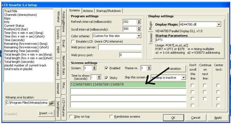
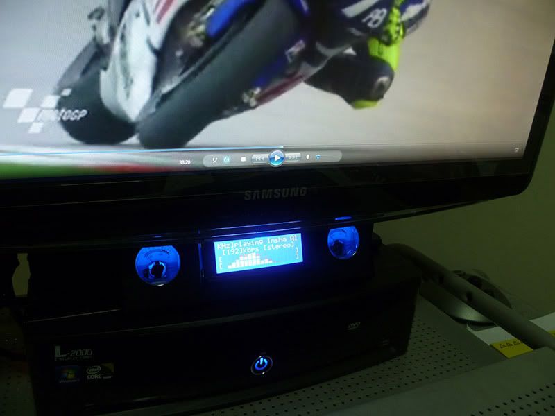
I did some searches and found this cool software called "LCD Smartie" and there are lots of cool videos on this topic in Youtube..

http://www.youtube.com/watch?v=zkW8VzkgtlI

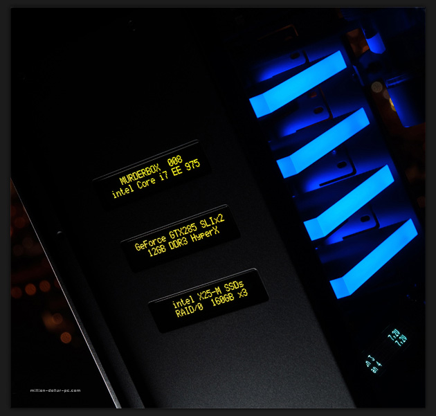
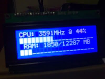
I find it pretty cool to output the winamp spectrum analyzer to the LCD module and you can also output stuff like upload/download speed, CPU, memory, hard disk space and other PC stats to the LCD...

This is very good when playing games or watching movies so that you know how much the CPU & memory is used up while in the game/movie...

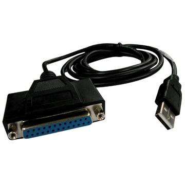
Best on Parallel port ( but not all modern desktop have it ) or go the USB method using either Arduino microcontroller or USB LCD ( still doing research on this one, if you know how to , pls share... )


Initially after getting an Arduino microcontroller, I did this setup using a USB/Serial connection to the LCD Module..

Attached Image

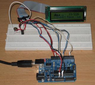
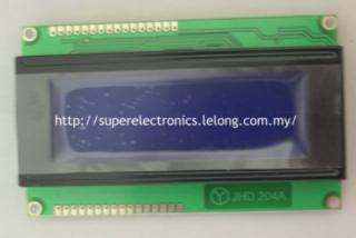
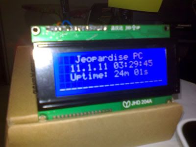
Later I was being more adventurous and got 2 version of the LCD Module, 2x16 and 4 x 20 ( line x columns )...and made this below ..

Attached Image

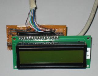
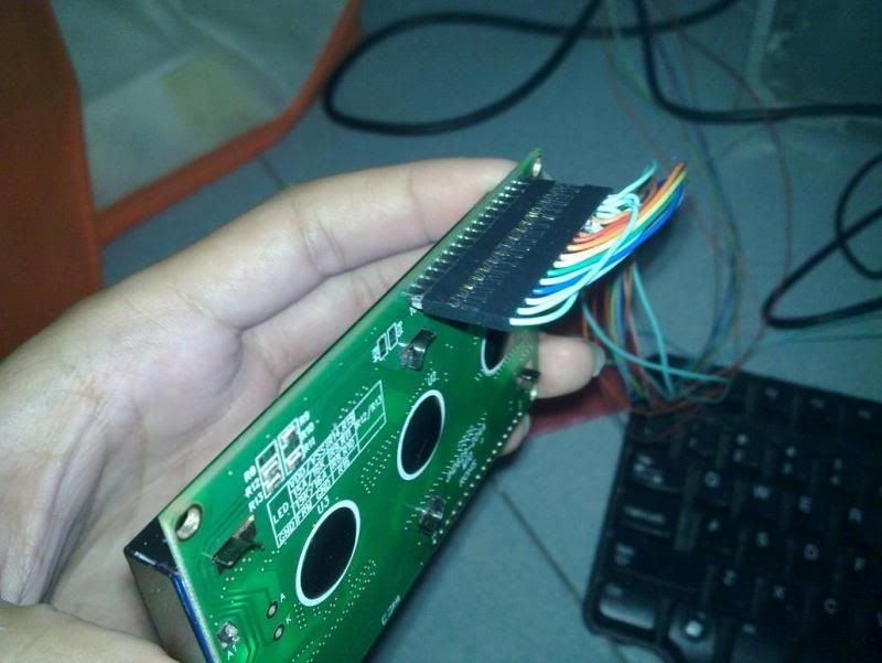
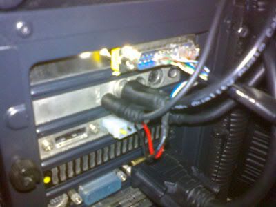
Board with LCD Module removed...

Attached Image

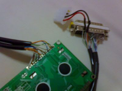
There are 10 cables connected to the parallel port and I am using UTP cables ( 4 pairs plus another 1 pairs, total 10 wires ). The other cable is the USB cable with one end cut off for the 5V power supply taken from USB hub or directly from the USB port...

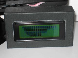
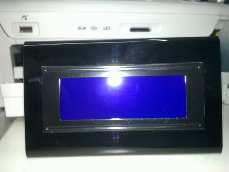
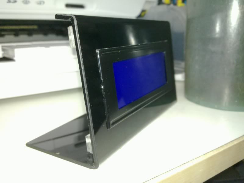
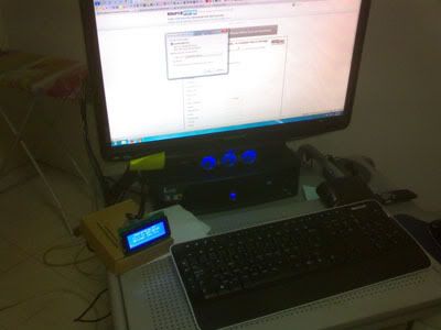
Later upgraded to a 4x20 LCD Module...

Attached Image

and put everything into a black cardboard box on top of my desktop just below the LCD monitor...

Attached Image


Parallel LCD wiring, credits goto the webpage below.. I just follow his wiring and did some modifications..
http://www.icehw.net/article.php?id=104

Feel free to ask any questions ...


Parts used ( all obtain locally in Jalan Pasar ) :-

2x16 or 4x20 LCD modules purchased from Jalan Pasar
1 x trimpot 10K resistors to control the contrast
Cat 5 UTP cables ( needed 10 wires - as long as you needed to connect from the parallel port to the desktop )
1 x USB cables with one end cut off for the 5V power
1 perf board
1 x 16 pin male header soldered to the LCD Module
1 x 16 pin female headrr on the perf board


A LYN forumer selling the 20x4 USB LCD product. The WTS link is here

This post has been edited by stan001: Feb 24 2012, 02:01 PM
supernothing
post Oct 2 2010, 02:48 AM

super ☆
******
Senior Member
1,343 posts

Joined: Jun 2006
From: Wangsa Maju/TTDI/Ampang


cool project, how much did you spend for all the stuffs? very interested in making one myself. what about the softwares? are they easily available for download?
lun1986
post Oct 2 2010, 10:58 AM

Enthusiast
*****
Senior Member
939 posts

Joined: Jan 2007
the LCD Module got backlight anot?
how much u spend on it ??

This post has been edited by lun1986: Oct 2 2010, 11:00 AM
TSstan001
post Oct 2 2010, 01:29 PM

On my way
****
Senior Member
623 posts

Joined: Jan 2003
From: Kuala Lumpur


The cost of everything is less than RM50 ... the LCD module is around RM40..

The software is LCD Smartie

The rest of the stuff like perf board, trimpot, perf board, pins and headers are all around RM1-2 only.. wires ( 10 pcs according to your own length ) ...

Forgot 1 parts : DB25 male + cover

http://www.bizchip-components.com/shop/ind...?productID=7528

Can solder directly from the DB25 male port ( parallel port ) to the LCD module and bypass the additional parts like perf board and header pins.. I made mine more portable as I can switch between 2x16 and 4x20 module..

There are a few online sellers if u r not located at Klang Valley..search for "LCD Module" on lelong.com.my

There are backlight on pin 15 & 16 but when I took the pic with flash, cannot "see" the backlight in the picture..


lun1986
post Oct 2 2010, 03:44 PM

Enthusiast
*****
Senior Member
939 posts

Joined: Jan 2007
the wires u use not Parallel cable ?
LCD module is around RM40.. <-- tis is 4 X 20 ??

TSstan001
post Oct 2 2010, 04:27 PM

On my way
****
Senior Member
623 posts

Joined: Jan 2003
From: Kuala Lumpur


Yes, RM40 for the 4x20 , the 2x16 is cheaper around RM20 only but less lines so less stuff can be displayed...

No, I did not use the parallel cables cos I have a lot of long Cat5 UTP cables around, I just strip off the rubber cover and took 10 wires...

The USB version ( for most ppl without Parallel port ) instruction is below if you can find the FTDI USB/Serial module locally...

http://forums.lcdsmartie.org/viewtopic.php?f=11&t=1540


supernothing
post Oct 3 2010, 02:38 PM

super ☆
******
Senior Member
1,343 posts

Joined: Jun 2006
From: Wangsa Maju/TTDI/Ampang


woahhh, i prefer the usb version. can do one for me?
mengsuan
post Oct 3 2010, 09:34 PM

9W2NNS
Group Icon
Staff
10,459 posts

Joined: Sep 2005
From: Puchong

I have two 4x20 blue backlight parallel LCD from my academic project. I wanted to interface to my computer but nowadays even x58 boards may not have parallel port anymore.

I don't do Arduino but only PIC microcontroller. I wonder if I can route serial data to a PIC microcontroller. Or does LCD smartie support demultiplexers directly from serial port?
TSstan001
post Oct 3 2010, 11:17 PM

On my way
****
Senior Member
623 posts

Joined: Jan 2003
From: Kuala Lumpur


I'm not sure what you mean by deMUX... the PIC controller should do the following functions like an Arduino :-

- Act as Serial USB to the computer
- Once the drivers are installed for the USB Serial adapter, LCD Smartie software should be able to talk to the Serial port directly using MatrixOrbital plugins ( Matrix Orbital makes serial LCDs )...

From their forum, they are using FTDI chipsets/module to wireup the Serial/USB LCD... the wiring looks pretty simply...

http://forums.lcdsmartie.org/viewtopic.php?f=11&t=1540

This module can be found locally (FTDI BASIC BREAKOUT 3.3/5V) but I have not tested if it is supported by LCD Smartie software or plugins..

http://www.myduino.com/index.php?route=pro...5&product_id=91


Added on October 8, 2010, 11:10 amUpdates :-

You can have LCD shield on an Arduino powered by a USB with 5 buttons for those that do not know how to do soldering or DIY stuff...

http://www.nuelectronics.com/estore/index....ject_lcdsmartie

or

http://www.instructables.com/id/Arduino-wi...artie-over-USB/


Found that there is current a bulk orders for the Arduino board and the LCD Shield..

http://forum.lowyat.net/index.php?showtopi...&#entry36288604

This post has been edited by stan001: Oct 8 2010, 11:12 AM
RonModz
post Oct 11 2010, 03:24 PM

Getting Started
**
Junior Member
199 posts

Joined: Apr 2010
From: Batu Caves


You can get the USB board here - http://www.cytron.com.my/viewProduct.php?p...33;!!A=
supernothing
post Oct 11 2010, 07:43 PM

super ☆
******
Senior Member
1,343 posts

Joined: Jun 2006
From: Wangsa Maju/TTDI/Ampang


further search led me to this.

http://www.lcdmodkit.com/index.html

you can buy ready made ldc kit with 5.25" bay cover, or buy by parts and DIY. your pick, price is pretty cheap and shipping is free brows.gif
m32t8103
post Oct 12 2010, 01:21 AM

New Member
*
Junior Member
15 posts

Joined: Dec 2009


=D well i have some question, do you think possible that Arduino LCD (the one with the keypad), could you make the software that work with the kepad? or using the kepad to control the software
TSstan001
post Oct 12 2010, 10:58 AM

On my way
****
Senior Member
623 posts

Joined: Jan 2003
From: Kuala Lumpur


YES it can control the LCD Smartie s/w according to the URL and the codes supplied ( since it is open source ), they did modified the LCD library to support the 5 buttons located on the LCD Shield. ( Arduino add-ons )

QUOTE
http://www.nuelectronics.com/estore/index....ject_lcdsmartie

3.2 Interrupt driven Keypad scanning routine
An interrupt driven Keypad scanning routine is used to capture key press from the Joystick keypad inputs. Timer2 is used to generate interrupt at 4ms interval. The interrupt routine records the key press by reading AD0 value and comparing with keypad value stored in an array. A debounce mechnism is also implemented. The interrupt routine then transfer the key press to LCD Smartie software running on the PC. The key press is useful for controlling PC applications, such as Winamp Player.
haris
post Oct 17 2010, 09:23 AM

Getting Started
**
Junior Member
172 posts

Joined: Dec 2005
From: KL


Hello Stanley,

Thanks for linking to my bulk thread.

Your USB FTDI Breakout Board is on the way (sometime next week). So you can plan to extend your circuit to include that.

Pardon me for putting advertisement here wink.gif

Arduino Duemilanove and Uno (the latest) are available from my web site shop>> H&T Shop

For those who want fast result without soldering and etching PCB. LCD Keypad Shield is also available for RM63. There is another type of display called LCD Graphic Shield. This is for graphical stuff and even have some connectors on top of it for sensors. Gonna blog about this soon!

I have one FTDI breakout board coming together with Stanley shipment. Since this is an extra you guys can have it form RM38 brows.gif.

For those in KL or nearby and interested to see a demo or stuff in action. I usually held some kind of demo and COD session in my Condo in 2 1/2 mile Jalan Ipoh (address and map refer to >> H&T Contact). PM me if you are interested to join in and I will let the first few people to know when. We are just starting so cannot accommodate more than 10 people at the moment.

Stanley, great article and I have read your Blog. Excellent stuff. As you already know (and pre registered for). I am trying to establish Malaysian Arduino homebrewing community at www.arduino-malaysia.com. If you are insterested, I can invite you and you can have your own www.arduino-malaysia.com/YourName blog there.

---
Disclaimer: H&T or www.homebrew-tech.com is Malaysia official distributor for Arduino. We are also appointed distributor for DFRobot product. Not just some trader. And as such obviously have commercial interest in all of the above listed item wink.gif


*Edit to add disclaimer

This post has been edited by haris: Oct 17 2010, 09:53 AM
azmax100
post Oct 20 2010, 12:19 PM

Getting Started
**
Junior Member
205 posts

Joined: Dec 2006


Thanks Stanley for the link.

Get your Arduino here http://myduino.com

Arduino Uno starter kit RM149.90 only. rclxms.gif

This post has been edited by azmax100: Oct 20 2010, 12:22 PM
TSstan001
post Oct 28 2010, 05:00 PM

On my way
****
Senior Member
623 posts

Joined: Jan 2003
From: Kuala Lumpur


Updates..

I've finally made a USB version of the LCD Module for LCD Smartie in bit-bang mode...

Attached Image
k3lvinng007
post Oct 28 2010, 05:29 PM

Casual
***
Junior Member
311 posts

Joined: Mar 2009


QUOTE(stan001 @ Oct 28 2010, 05:00 PM)
Updates..

I've finally made a USB version of the LCD Module for LCD Smartie in bit-bang mode...

Attached Image
*
video pls... rclxms.gif
btw for USB version how much it cost u?
TSstan001
post Oct 29 2010, 09:45 AM

On my way
****
Senior Member
623 posts

Joined: Jan 2003
From: Kuala Lumpur


Updated photos with nicer wiring...

LCD module is 4x20

Attached Image

Note - Backlight is on but the flash have covered the light..


lun1986
post Oct 29 2010, 10:36 AM

Enthusiast
*****
Senior Member
939 posts

Joined: Jan 2007
nice try, all the part u buy from jln pasar ?
TSstan001
post Oct 29 2010, 10:48 AM

On my way
****
Senior Member
623 posts

Joined: Jan 2003
From: Kuala Lumpur


Most parts except for the FTDI board...

Can you make something like this with Arcylic like the Youtube below...

Dunno what materials they use ...
http://www.youtube.com/watch?v=pJ9y3uAZlYo


lun1986
post Oct 29 2010, 01:49 PM

Enthusiast
*****
Senior Member
939 posts

Joined: Jan 2007
can, the material name "Arcylic" biggrin.gif
janagen
post Oct 30 2010, 02:05 PM

New Member
*
Junior Member
35 posts

Joined: Oct 2010


bro can make 1 for me ??? lol
TSstan001
post Oct 30 2010, 06:07 PM

On my way
****
Senior Member
623 posts

Joined: Jan 2003
From: Kuala Lumpur


QUOTE(lun1986 @ Oct 29 2010, 01:49 PM)
can, the material name "Arcylic" biggrin.gif
*
Yes, i know.. how to cut it according to the size I needed ?

Never deal with arcylic before leh..

I hv both B&D elec drill and B&D RTX "dremel" ... can I use these tools to cut it ??

Thanks
ryudox
post Oct 30 2010, 08:05 PM

~~ ConVict ~~
*****
Senior Member
732 posts

Joined: Nov 2004
From: where to where...


have u tried using old phone screen such as nokia 3310? i have a lot but dont know how to use it...lolz
lun1986
post Oct 30 2010, 08:21 PM

Enthusiast
*****
Senior Member
939 posts

Joined: Jan 2007
erm, many method to cut
jigsaw, laser, cnc machine, choppin saw,.....the tool u got not suitable to cut
TSstan001
post Oct 30 2010, 09:50 PM

On my way
****
Senior Member
623 posts

Joined: Jan 2003
From: Kuala Lumpur


QUOTE(ryudox @ Oct 30 2010, 08:05 PM)
have u tried using old phone screen such as nokia 3310? i have a lot but dont know how to use it...lolz
*
Did some searches and found the following for you :-

Arduino codes and library :-
http://www.arduino.cc/playground/Code/PCD8544


Nokia 3310 display uses the below driver :-
http://www.myplace.nu/mp3/files/pcd8544.pdf

Schematics to connect an ATMEGA to the nokia display module..
http://www.flickr.com/photos/fallens/120708373/


lun1986
post Oct 30 2010, 10:23 PM

Enthusiast
*****
Senior Member
939 posts

Joined: Jan 2007
is tis all code for free source user/developer??
TSstan001
post Nov 1 2010, 04:31 PM

On my way
****
Senior Member
623 posts

Joined: Jan 2003
From: Kuala Lumpur


QUOTE(lun1986 @ Oct 30 2010, 10:23 PM)
is tis all code for free source user/developer??
*
All the Arduino codes are open source and freely available , you can modify it anyway you like...


nkarul85
post Nov 1 2010, 06:29 PM

newbies
******
Senior Member
1,480 posts

Joined: Mar 2009
From: puchong, selangor


if less that rm50 can make for us? tongue.gif
haha nice2

keep update here woo
lun1986
post Nov 17 2010, 12:00 AM

Enthusiast
*****
Senior Member
939 posts

Joined: Jan 2007
finally my lcd is done, big thanks to bro stan biggrin.gif

stan, y the 1st line of sentence will continue to 3rd line but not 2nd line ??

user posted image

user posted image

This post has been edited by lun1986: Nov 17 2010, 12:01 AM
TSstan001
post Nov 17 2010, 12:30 AM

On my way
****
Senior Member
623 posts

Joined: Jan 2003
From: Kuala Lumpur


Make sure you set the screen size correctly..

You LCD module looks like a 20x4, under the Display Setting below the Plugin tab, Click on the Screen tab and choose the correct display type (20x4)

You can lower yr refresh interval for faster graphs response , especially the winamp plugins... I can go as low as 40-50ms for the parallel port version..

White on Blue looks pretty nice LCD..


lun1986
post Nov 17 2010, 08:02 AM

Enthusiast
*****
Senior Member
939 posts

Joined: Jan 2007
thanks bro, problem solve
btw tis is how i connect
user posted image
TSstan001
post Nov 19 2010, 01:00 PM

On my way
****
Senior Member
623 posts

Joined: Jan 2003
From: Kuala Lumpur


Nice and colourful cables.. smile.gif

Make an Arcylic stand for yr LCD module ??


lun1986
post Nov 19 2010, 03:20 PM

Enthusiast
*****
Senior Member
939 posts

Joined: Jan 2007
updated, brows.gif
user posted image
user posted image
amie_the_fakes3
post Nov 21 2010, 08:04 PM

Getting Started
**
Junior Member
277 posts

Joined: Aug 2010
how much to make whole set...
sweat.gif
supernothing
post Nov 21 2010, 11:27 PM

super ☆
******
Senior Member
1,343 posts

Joined: Jun 2006
From: Wangsa Maju/TTDI/Ampang


got mine running. bought the ready made lcd direct from hong kong. just plug and play. hit a snag during testing. i can't add a second lcd. can't find a way to make it work. i can't control the second lcd. any ideas? loading 2 lcd smartie program doesn't help.

user posted image

user posted image
TSstan001
post Nov 22 2010, 12:55 AM

On my way
****
Senior Member
623 posts

Joined: Jan 2003
From: Kuala Lumpur


Why would u want to add a 2nd LCD ?

Just get a bigger LCD la... it is not like dual monitor la..

I dun think most s/w would support dual LCD... or most USB chip does not have enuf pins to drive two LCD...


supernothing
post Nov 22 2010, 01:13 AM

super ☆
******
Senior Member
1,343 posts

Joined: Jun 2006
From: Wangsa Maju/TTDI/Ampang


the reason for 2 lcd is to do something like this

user posted image

taken from http://www.million-dollar-pc.com/systems-2...8/murderbox.htm

This post has been edited by supernothing: Nov 22 2010, 01:14 AM
lun1986
post Nov 22 2010, 10:27 AM

Enthusiast
*****
Senior Member
939 posts

Joined: Jan 2007
@supernothing
load 2 lcd smartie, with diff plugin ??

y dun do a bulk, sure many ppl in.
supernothing
post Nov 22 2010, 10:38 PM

super ☆
******
Senior Member
1,343 posts

Joined: Jun 2006
From: Wangsa Maju/TTDI/Ampang


QUOTE(lun1986 @ Nov 22 2010, 10:27 AM)
@supernothing
load 2 lcd smartie, with diff plugin ??

y dun do a bulk, sure many ppl in.
*
i have tried loading 2 instance of lcd smartie, no luck.

bulk buy? malas laa, anybody that wants it can buy direct from the website. they take paypal. can arrive here in less than a week.
TSstan001
post Nov 22 2010, 11:50 PM

On my way
****
Senior Member
623 posts

Joined: Jan 2003
From: Kuala Lumpur


QUOTE(supernothing @ Nov 22 2010, 01:13 AM)
the reason for 2 lcd is to do something like this

[snip...]
If you just need static display or repeating loop of characters, it can be easily done with an Arduino / Atmel ATMEGA 328 microcontroller/chip with Normal LCD Module (no need USB version)

Just wire up all the pins and loop it.. no need LCD Smartie to send in the dynamic data..

Only need the following... ( not tested but should work...)

Tap +5V & Gnd from molex connector to the following :-


Atmega 328 pins to LCD Module pins :-

Gnd - 1
+5V - 2
Pot - 3
18 - 4
Gnd - 5
17 - 6
11 - 11 (D4)
12 - 12 (D5)
13 - 13 (D6)
14 - 14 (D7)
+5V - 15 (backlight)
Gnd - 16 (backlight)

If you need 2 to 3 temp sensors, you can add them to the free analog pins...

Attached is the pic with Atmega 328 with LCD module as per the above pins with a IR range sensors, you can easily replaced it with temp sensors..

Attached Image

Ignore the left portion (voltage regulator) as the molex already supply +5V to the chip and the left most chip as it is used to program the chip using serial RS-232

This post has been edited by stan001: Nov 22 2010, 11:55 PM
supernothing
post Nov 23 2010, 09:14 AM

super ☆
******
Senior Member
1,343 posts

Joined: Jun 2006
From: Wangsa Maju/TTDI/Ampang


that pic looks complicated with all the wiring. my lcd module came with pre installed/wired usb connection. might need an extra chip, flash it with whatever i want to display and let it run in loops. might work, i'll look for the solution.

thanks
TSstan001
post Nov 23 2010, 10:56 AM

On my way
****
Senior Member
623 posts

Joined: Jan 2003
From: Kuala Lumpur


Yes, that what the Arduino / ATMEGA328 (or similar ATMEL) chip does..

Breadboard are for prototyping... usually the finished product will look much neater with all the cables soldered directly from the chip to the LCD module..

And it does it very easily and lots and lots of people are doing it all over the world ( so no issues if u run into a problem ) and a lot of supplier of Arduino in Malaysia too..

Just google for "Arduino LCD" .... the version I posted/suggest to you is without the Arduino board but still the chip (Atmega328) so it is much lower cost..

Need help just let me know.. ok

Add-on for my reply :-

If you have a free serial port free, you can have the TX & RX port from the serial port connected to the Atmega/Arduino via the Max232 (the smaller chip in the picture ) and when you need to change the display on the LCD, just use a serial terminal program like Hyperterminal (or similar) to the serial port,they in the text and disconnect.

Can easily program the Arduino to listen to serial port and loop the display to the LCD module...


This post has been edited by stan001: Nov 23 2010, 06:59 PM
limhongwoon
post Dec 23 2010, 12:49 PM

Intel Certified - COre I7
*******
Senior Member
2,892 posts

Joined: Oct 2007
From: Penang


Where can I find colour LCD ?
TSstan001
post Dec 23 2010, 12:55 PM

On my way
****
Senior Member
623 posts

Joined: Jan 2003
From: Kuala Lumpur


QUOTE(limhongwoon @ Dec 23 2010, 12:49 PM)
Where can I find colour LCD ?
*
Try this site :-
http://www.winstar.com.tw/products.php

Or just get those mini 7"or larger LCD with VGA ports... powered from the PC...

Usually for microcontroller and small device, it is powered by a single colour LCD module.. smile.gif


limhongwoon
post Dec 25 2010, 07:42 PM

Intel Certified - COre I7
*******
Senior Member
2,892 posts

Joined: Oct 2007
From: Penang


user posted image

The MurderBox is using what type of LCD ? 16x2 Character LCD or 20X4 Character LCD ? One USB can connect how many LCD ?
TSstan001
post Dec 26 2010, 10:22 AM

On my way
****
Senior Member
623 posts

Joined: Jan 2003
From: Kuala Lumpur


QUOTE(limhongwoon @ Dec 25 2010, 07:42 PM)
user posted image

The MurderBox is using what type of LCD ? 16x2 Character LCD or 20X4 Character LCD ? One USB can connect how many LCD ?
*
If you count the longest text display on the LCD, it is around 20 characters... but have 2 lines only... 20 x 2 type or longer...

I think he is using a uncommon LCD module ...

From the URL, I saw that the fellow hv another LCD inside the case to display all the temp and such and the three LCD at the front are static LCD only..

So my guess is that those 3 LCD are static display only and the text does not change ... no need to use USB, just wire up a microcontroller to the LCD, send the codes/programming to the microcontroller with the text

line 1 " Super Duper Mod 002"
line 2 "Intel Core i 7 xx 888"

and power it up from the +5V molex with some resistors.. totally not connected to the PC at all...

When you need to change the text, just plug in the USB/Serial TTL and re-programme it... I've an article on my blog/facebook page on it..

Each Arduino microcontroller could drive like 1 LCD bcos each LCD would take up 3 control pins and 4 data pins...

If you needed 3 Arduino for this purpose with LCD module, I can make them for you cheaply if you are intertested...


Added on December 26, 2010, 10:23 am
QUOTE(limhongwoon @ Dec 25 2010, 07:42 PM)
user posted image

The MurderBox is using what type of LCD ? 16x2 Character LCD or 20X4 Character LCD ? One USB can connect how many LCD ?
*
If you count the longest text display on the LCD, it is around 20 characters... but have 2 lines only... 20 x 2 type or longer...

I think he is using a uncommon LCD module ...

From the URL, I saw that the fellow hv another LCD inside the case to display all the temp and such and the three LCD at the front are static LCD only..

So my guess is that those 3 LCD are static display only and the text does not change ... no need to use USB, just wire up a microcontroller to the LCD, send the codes/programming to the microcontroller with the text

line 1 " Super Duper Mod 002"
line 2 "Intel Core i 7 xx 888"

and power it up from the +5V molex with some resistors.. totally not connected to the PC at all...

When you need to change the text, just plug in the USB/Serial TTL and re-programme it... I've an article on my blog/facebook page on it..

Each Arduino microcontroller could drive like 1 LCD bcos each LCD would take up 3 control pins and 4 data pins...

If you needed 3 Arduino for this purpose with LCD module, I can make them for you cheaply if you are intertested...


This post has been edited by stan001: Dec 26 2010, 10:23 AM
limhongwoon
post Dec 26 2010, 11:25 AM

Intel Certified - COre I7
*******
Senior Member
2,892 posts

Joined: Oct 2007
From: Penang


QUOTE(stan001 @ Dec 26 2010, 11:22 AM)
If you count the longest text display on the LCD, it is around 20 characters... but have 2 lines only... 20 x 2 type or longer...

I think he is using a uncommon LCD module ...

From the URL, I saw that the fellow hv another LCD inside the case to display all the temp and such and the three LCD at the front are static LCD only..

So my guess is that those 3 LCD are static display only and the text does not change ... no need to use USB, just wire up a microcontroller to the LCD, send the codes/programming to the microcontroller with the text

line 1 " Super Duper Mod 002"
line 2 "Intel Core i 7 xx 888"

and power it up from the +5V molex with some resistors.. totally not connected to the PC at all...

When you need to change the text, just plug in the USB/Serial TTL and re-programme it... I've an article on my blog/facebook page on it..

Each Arduino microcontroller could drive like 1 LCD bcos each LCD would take up 3 control pins and 4 data pins...

If you needed 3 Arduino for this purpose with LCD module, I can make them for you cheaply if you are intertested...


Added on December 26, 2010, 10:23 am

If you count the longest text display on the LCD, it is around 20 characters... but have 2 lines only... 20 x 2 type or longer...

I think he is using a uncommon LCD module ...

From the URL, I saw that the fellow hv another LCD inside the case to display all the temp and such and the three LCD at the front are static LCD only..

So my guess is that those 3 LCD are static display only and the text does not change ... no need to use USB, just wire up a microcontroller to the LCD, send the codes/programming to the microcontroller with the text

line 1 " Super Duper Mod 002"
line 2 "Intel Core i 7 xx 888"

and power it up from the +5V molex with some resistors.. totally not connected to the PC at all...

When you need to change the text, just plug in the USB/Serial TTL and re-programme it... I've an article on my blog/facebook page on it..

Each Arduino microcontroller could drive like 1 LCD bcos each LCD would take up 3 control pins and 4 data pins...

If you needed 3 Arduino for this purpose with LCD module, I can make them for you cheaply if you are intertested...
*
Where got sell the Static Display ?
techi5
post Dec 27 2010, 03:28 PM

Getting Started
**
Junior Member
127 posts

Joined: Nov 2009


can use scientific calculator display? mine is fx-570ms! ned to know b4 2011. few days holiday for me to do biggrin.gif thanks!
TSstan001
post Dec 27 2010, 05:54 PM

On my way
****
Senior Member
623 posts

Joined: Jan 2003
From: Kuala Lumpur


It is cheaper to buy a LCD module than to salvage from a calculator...

Anyway, the calculator is numeric, not alphanumeric..


techi5
post Dec 28 2010, 12:57 AM

Getting Started
**
Junior Member
127 posts

Joined: Nov 2009


what about a touchscreen lcd from besta dictionary? mine's broken, but i'm 100% sure the lcd is working smile.gif can?
TSstan001
post Dec 28 2010, 02:41 AM

On my way
****
Senior Member
623 posts

Joined: Jan 2003
From: Kuala Lumpur


QUOTE(techi5 @ Dec 28 2010, 12:57 AM)
what about a touchscreen lcd from besta dictionary? mine's broken, but i'm 100% sure the lcd is working smile.gif can?
*
Are you able to get the specs or datasheet of the LCD used in the besta ?

The ones Arduino usually use are all using HD44780-compatible LCD ..

More of the type of display supported at : http://www.arduino.cc/playground/Code/LCD

All the supported ones will have its libraries..


jeopardise
post Dec 31 2010, 10:41 PM

tidak memberi seketul tahi!
******
Senior Member
1,767 posts

Joined: Jan 2003
From: Bandar Seri Putra


I think I will get one soon.

Perhaps trying parallel port first, then if OK, should try USB method.

However I might need PCI parallel card as my motherboard doesnt have LPT.


Do you think using USB to parallel port convertor works with this?

user posted image

This post has been edited by jeopardise: Jan 1 2011, 11:01 AM
old timer
post Jan 2 2011, 12:21 PM

New Member
*
Newbie
4 posts

Joined: Aug 2010
nice elektrical n elektronik job here...nak belajar dgn expert la...hehe
TSstan001
post Jan 2 2011, 01:14 PM

On my way
****
Senior Member
623 posts

Joined: Jan 2003
From: Kuala Lumpur


QUOTE(old timer @ Jan 2 2011, 12:21 PM)
nice elektrical n elektronik job here...nak belajar dgn expert la...hehe
*
Do you want to learn about electronics ? I can give you some guidance...

I'm just a very curious hobbyists on how things work.. smile.gif


jeopardise
post Jan 6 2011, 06:29 PM

tidak memberi seketul tahi!
******
Senior Member
1,767 posts

Joined: Jan 2003
From: Bandar Seri Putra


Mines not working. I've followed exactly like http://www.icehw.net/article.php?id=104 wiring diagram.

Double checked and still nothing come out.

I bought a LCD module from super electronic@lelong model JHD 204A

Attached Image

I bought a cheap PCI parallel port and my PC specs are as my signature. Perhaps the PCI card isn't a true parallel hardware. I will try on other machine soon.

How to use LCD smartie softare? I mean the parameter. It seems my LPT1 port have E880-E887


This post has been edited by jeopardise: Jan 6 2011, 07:35 PM
TSstan001
post Jan 6 2011, 10:34 PM

On my way
****
Senior Member
623 posts

Joined: Jan 2003
From: Kuala Lumpur


When LCD boot up, it should show a full bar on all the lines, you use the preset/trimpot on pin3 to adjust the contrast until you can see the BLACK bars.

Make sure all the Ground are connected.

LCD Smartie settings for LPT :-
Display Plugins is HD44780
Startup parameter = $E880

You need a software to make yr parallel port accessable on Win7. It is called port95nt.


jeopardise
post Jan 7 2011, 10:30 AM

tidak memberi seketul tahi!
******
Senior Member
1,767 posts

Joined: Jan 2003
From: Bandar Seri Putra


I still have trouble to access LPT port using Windows 7. icon_question.gif

Now at the office I am using Win 7 32 bit while at home I''be using Win 7 x64.

Tried port95nt and INpout32.dll (said to support 64-bit) ... still not working.

However when my LCD turned on it'll show like in the photo. Line 1 and 3 appears darker than 2 and 4. Izzit normal? When I upped the voltage supply to 6V using 6x1.5 alkaline battery, all spaces appear at the same brightness.

Attached Image

Once this is successful, I'll be confident to try using Arduine bit USB.

Hope Google helps me find the answer soon hmm.gif
TSstan001
post Jan 7 2011, 11:11 AM

On my way
****
Senior Member
623 posts

Joined: Jan 2003
From: Kuala Lumpur


For testing/running, try to use Power Adapter ( 5V ) with the correct current ratings... if you have multimeter, pls test the output voltage first...

You need to read the datasheet ( search google or seller ) and see the specs for MAX voltage and current requirements..

Using battery is not consistence as voltage will drop over time/usage...

I cut an extra USB cable and draw the power from USB ( red wire is +5V, black cable is Ground ) directly from the PC USB port...

Draw power from the Molex connector from PC Power Supply , Red is +5V, Black is Ground... dun use Yellow as they are +12V !!!

Another idea is find those extra Nokia/Ericson Mobile charger, some of them are small and rated at 5V.. just nice for this..


Good luck!!!!


jeopardise
post Jan 7 2011, 11:42 AM

tidak memberi seketul tahi!
******
Senior Member
1,767 posts

Joined: Jan 2003
From: Bandar Seri Putra


At 5 volts from molex (YES I connects to the red line)


Line 1 and 3 appears darker than 2 and 4. Izzit normal?

In addition, it appears that my LCU module quite different from usual LCD that I can find. This one has 16 golden fingers on top and at the bottom. All the same?

This post has been edited by jeopardise: Jan 7 2011, 12:06 PM
TSstan001
post Jan 7 2011, 12:00 PM

On my way
****
Senior Member
623 posts

Joined: Jan 2003
From: Kuala Lumpur


QUOTE(jeopardise @ Jan 7 2011, 11:42 AM)
At 5 volts from molex (YES I connects to the red line)
Line 1 and 3 appears darker than 2 and 4. Izzit normal?
*
No, it is NOT normal.. but you mention if voltage is 6V, then it shows all even brightness...

If power is sufficient, then it should NOT show uneven lines... use the trimpot connected to pin 3 to adjust until all show the darkness evenly..

You might need current limiting resistor on pin 15 & 16 bcos current from the molex is quite high... (it might work but it would reduce the life of the LCD )


jeopardise
post Jan 7 2011, 05:05 PM

tidak memberi seketul tahi!
******
Senior Member
1,767 posts

Joined: Jan 2003
From: Bandar Seri Putra


I will try to find a trimpot to control the contrast. I usually salvage components from damaged electronic parts tongue.gif

May the FORCE be with me!

This post has been edited by jeopardise: Jan 8 2011, 01:32 PM
jeopardise
post Jan 8 2011, 01:33 PM

tidak memberi seketul tahi!
******
Senior Member
1,767 posts

Joined: Jan 2003
From: Bandar Seri Putra


]Hi stanley,

Could you show me a simple wiring diagram to control the contrast? tq

It seems my LCD module issue has been discussed here. See what can I do hmm.gif

This post has been edited by jeopardise: Jan 8 2011, 01:43 PM
TSstan001
post Jan 8 2011, 02:21 PM

On my way
****
Senior Member
623 posts

Joined: Jan 2003
From: Kuala Lumpur


Pic is here :-
Like this : http://arduino-for-beginners.blogspot.com/...les-part-1.html

Potentiometer or trimpot have 3 pins.. ( voltage divider )

Connect pin 1 to 5V
Connect pin 2 to pin 3 of LCD
Connect pin 3 to ground

Adjust the pot until you get all BLACK bar...


jeopardise
post Jan 8 2011, 02:37 PM

tidak memberi seketul tahi!
******
Senior Member
1,767 posts

Joined: Jan 2003
From: Bandar Seri Putra


in my case, the LCD has blue backlight .

So BLACK bar means the bar darker than the backlight OR brighter than backlight?

Attached Image

should appear white right?


Added on January 8, 2011, 3:03 pmI googled around and found this:

QUOTE
Quote:
I then tried using the LCD4Bit library and example sketch, but all i get are 2 lines of black squares on the 1st & 3rd line, and the compiler didn't show any problem before upload.

When you get the two lines of black squares it means that you have the power applied and the contrast set properly but the LCD controller has not been initialized properly. 

Many of the libraries that are available do not follow the datasheet recommendations to use software initialization or they do not implement that initialization properly. 

I suggest you try the latest official LiquidCrystal library (Arduino v0017) and try the accompanying example programs.  This library follows the datasheet more closely than all the others and should work for you.

Don


From: http://www.arduino.cc/cgi-bin/yabb2/YaBB.p...=1251279124/6#6

QUOTE
When you say it goes to full bars, do you mean ?

I had an issues where i got the lines of black squared on lines 1 & 3 of the LCD which meant it wasn't initializing the screen. which i suspect is the same for you.

Make sure you have the lcd initialized with the following code, and just make sure the pins defined match the input/output pins you are using ?

Quote:
// initialize the library with the numbers of the interface pins
LiquidCrystal lcd(12, 11, 5, 4, 3, 2);


It seems this LCD is a bit different. Looks like I have to program the LCD to initialize it properly.

I think I wanna buy 2x20 module that u're using perhaps can work out of the box. Not so ready to do some programming though cry.gif

Another issue here : http://translate.google.com/translate?js=n...php%3Ft%3D28415

Looks like it's not the contrast problem. I have tried to arjust with the pot, no change. rclxub.gif

This post has been edited by jeopardise: Jan 8 2011, 03:12 PM
TSstan001
post Jan 8 2011, 11:57 PM

On my way
****
Senior Member
623 posts

Joined: Jan 2003
From: Kuala Lumpur


QUOTE(jeopardise @ Jan 8 2011, 02:37 PM)
in my case, the LCD has blue backlight .

So BLACK bar means the bar darker than the backlight OR brighter than backlight?

Attached Image

should appear white right?
Yes, it should be WHITE for yr case... smile.gif

I've a 4x20 LCD Black on Green, YES, it should be line 1 & 3 lit up full bar ...

I use a voltmeter to measure pin 3, the voltage is very small, in mV, so if you want full bar, just ground it for 0V.. and skip the trimpot... like the website you mentioned.

All these character based LCD are using the HD44780 protocol... can be different sizes, 16x2 20x4 or 40x2... all the same way of driving it..

Pin 15 & 16 are for the backlight, connect 15 to Ground and 16 to 5V..

*** Some of these LCD, the viewing angle is small, it will look full brightness (or darkness) at direct angle and looks dimmer at different angle..


jeopardise
post Jan 9 2011, 10:30 AM

tidak memberi seketul tahi!
******
Senior Member
1,767 posts

Joined: Jan 2003
From: Bandar Seri Putra


QUOTE(stan001 @ Jan 8 2011, 11:57 PM)
Yes, it should be WHITE for yr case... smile.gif

Pin 15 & 16 are for the backlight, connect 15 to Ground and 16 to 5V..
pin 15 should be power +5v while pin 16 should be ground right?
TSstan001
post Jan 9 2011, 10:57 AM

On my way
****
Senior Member
623 posts

Joined: Jan 2003
From: Kuala Lumpur


QUOTE(jeopardise @ Jan 9 2011, 10:30 AM)
pin 15 should be power +5v while pin 16 should be ground right?
*
Usually...on the datasheet, they are called Cathode(K) & Anode(A) (similar to a LED) but I've one LCD with the K & A reversed.

If one way did not work, just swap it around..

So did you managed to get the LCD working for LCDSmartie software yet ?

My case when I first constructed the Parallel port version, I had some grounding issues, so I need to trace all the cables...

Post some pics of your circuits with the LCD


jeopardise
post Jan 9 2011, 12:01 PM

tidak memberi seketul tahi!
******
Senior Member
1,767 posts

Joined: Jan 2003
From: Bandar Seri Putra


All right, I will post some pics later.

To make the LPT1 port, I might use VMware with Windows XP as client. Porting the LPT1 to host LPT1 might work or for the last resort I might install Windows XP 32bit natively. This is because port95nt incompatible with Windows 7 x64. If it work with XP just to confirm the LCD working, I'll try other dlls to make it work in 64bit.

My soldering iron just died while I am trying to rebuild my wiring vmad.gif . Until I get a new one.

This post has been edited by jeopardise: Jan 11 2011, 09:43 AM
jeopardise
post Jan 11 2011, 09:44 AM

tidak memberi seketul tahi!
******
Senior Member
1,767 posts

Joined: Jan 2003
From: Bandar Seri Putra


Thanks stan001 for your helps.

At last it worked! rclxms.gif

1. Using VMware with LPT1 emulation with Windows XP client: The method to confirm LCD module and wiring is correct with port95nt (only works for 32bit windows) drivers.

Seems like the parallel black bar will automatically gone when the parallel port initialized by LCD smartie.


2. Using inpout32.dll (supporting x64 OS) now works (after some try and error)

The correct method is to copy Inpout32.dll for Windows 98/2000/NT/XP
into LCD Smartie root folder (overwrite the existing inpout32.dll) and renaming another copy of it to DLPortIO.DLL in the same folder.

QUOTE
Notes:
From Version 1.0.0.7, I have added, simple compatibility with DLPortIO that should allow LCDSmartie to use this DLL as a drop in replacement for DLPortIO in x64 windows. To do this, download just the binaries only package (below) then take the 32bit DLL (in the \Win32 folder), rename it to DLPortIO.DLL and copy it to your LCDSmartie folder. Read the DLPortIO.TXT file included in the ZIP for more information.

I have had confirmation that 1.0.0.7 works with LCDSmartie in Windows 2003 x64 using the above method.


You may get a "side by side" error when running Installdriver.exe on Vista (especially 64bit Vista). If you do, you can try downloading the latest Microsoft C++  runtimes (2005 SP1). For the 32bit version, go here. For the 64bit version, go here.
Some photos brows.gif

user posted imageuser posted image
My wiring using CAT5 cables from backyard. 5V power taken from molex +5v power from e-SATA power bracket.

user posted imageuser posted image


I think I will go for USB version soon. At the moment I am waiting for an extra 2x16 LCD module already otw to my address. Perhaps I wanna make this one to display static text. I also will do a housing for the LCD module to attach it to my PC. thumbup.gif thumbup.gif

This post has been edited by jeopardise: Jan 13 2011, 05:43 PM
TSstan001
post Jan 11 2011, 12:03 PM

On my way
****
Senior Member
623 posts

Joined: Jan 2003
From: Kuala Lumpur


QUOTE(jeopardise @ Jan 11 2011, 09:44 AM)
Thanks stan001 for your helps.

At last it worked!  rclxms.gif
rclxms.gif rclxms.gif

Yes, Vmware surely works cos I did mine on WinXP on a Mac via Vmware Fusion...

For acrylic case look for lun1986 ..

Sometimes, if we manage to fixed the issue , you will learn more about how it works!!! Or else we just blindly follow the HOWTO without knowing what is going on..

I m researching to do "static LCD" with the lowest possible cost using DIY Arduino microcontroller + LCD only.. stay tuned...


jeopardise
post Jan 11 2011, 01:20 PM

tidak memberi seketul tahi!
******
Senior Member
1,767 posts

Joined: Jan 2003
From: Bandar Seri Putra


Hi stan001 smile.gif,

U r right! Once it works, it seems this is so easy.

I hope I could find the USB FTDI chip like yours. It seems it also supported on MacOX and have device driver for it. Until I got budget for it, I'll personally ask for you recommendations later.

Arduino UNO also not bad. I'll definitely need one as it'll eliminate the use of PCI slot for LPT, less wiring troubles and also less hassle to enable the device in 64-bit.

In my case, I can't make it work by using "LPT1" parameter in LCDSmartie.exe. It is recognised by HD44780.dll by using address "$E880"
jeopardise
post Jan 20 2011, 11:27 AM

tidak memberi seketul tahi!
******
Senior Member
1,767 posts

Joined: Jan 2003
From: Bandar Seri Putra


I've made a proper housing for the LCD module and add 2 analogue VU meter from Coolermaster Musketeer. rclxms.gif Internally, there are two completely different circuits actually.

user posted image

With perf, fanspeed, aida64, winamp and keyboard shortcut plugins for LCD smartie, it totally rawks rclxm9.gif
dakwan5555
post Feb 23 2011, 06:07 AM

Getting Started
**
Junior Member
85 posts

Joined: Jul 2009


I'm interested in doing this. Do you do supply of the set? How much is the damage? smile.gif
TSstan001
post Feb 23 2011, 11:36 AM

On my way
****
Senior Member
623 posts

Joined: Jan 2003
From: Kuala Lumpur


QUOTE(dakwan5555 @ Feb 23 2011, 06:07 AM)
I'm interested in doing this. Do you do supply of the set? How much is the damage? smile.gif
*
I'm just posting a DIY solution to add LCD to yr desktop, not really selling it cos it is more fun to do it DIY style and you can customise it anyway you like it..

I think I've posted the parts and estimated cost in the beginning few posts...

You would need some basic soldering skills and can blindly follow the instructions without knowing what is going on..


dakwan5555
post Feb 23 2011, 12:37 PM

Getting Started
**
Junior Member
85 posts

Joined: Jul 2009


QUOTE(stan001 @ Feb 23 2011, 11:36 AM)
I'm just posting a DIY solution to add LCD to yr desktop, not really selling it cos it is more fun to do it DIY style and you can customise it anyway you like it..

I think I've posted the parts and estimated cost in the beginning few posts...

You would need some basic soldering skills and can blindly follow the instructions without knowing what is going on..
*
Sorry bro, here in Perak we have no kedai/dealer selling those electronic components in kit form... I just want it in the kit form.
dchew
post Feb 24 2011, 12:43 AM

Casual
***
Junior Member
325 posts

Joined: Jan 2008
From: somewhere i belong


nice guide, sarawak here dont have it also.
jeopardise
post Mar 8 2011, 10:00 PM

tidak memberi seketul tahi!
******
Senior Member
1,767 posts

Joined: Jan 2003
From: Bandar Seri Putra


try getting one from lelong.com.my.

I directly call/sms the seller for quick response biggrin.gif

I still have one 16x2 module haven't utilized. Perhaps i'll connect it to the office PC. I haven't tried the USB kits.

This post has been edited by jeopardise: Mar 8 2011, 10:03 PM
amir93
post Mar 9 2011, 02:39 PM

Getting Started
**
Junior Member
234 posts

Joined: Nov 2010
From: Alor Setar/Ayer Keroh


im interested but have no idea what is going on. any help sifu how to start the project ?
jeopardise
post Mar 17 2011, 12:03 AM

tidak memberi seketul tahi!
******
Senior Member
1,767 posts

Joined: Jan 2003
From: Bandar Seri Putra


QUOTE(amir93 @ Mar 9 2011, 02:39 PM)
im interested but have no idea what is going on. any help sifu how to start the project ?
*
what do you have got so far?
TSstan001
post Mar 17 2011, 01:17 AM

On my way
****
Senior Member
623 posts

Joined: Jan 2003
From: Kuala Lumpur


I got PM that fellow.. but "no sound no breath" at all..


eric_tan
post Oct 24 2011, 12:20 AM

Getting Started
**
Junior Member
264 posts

Joined: Feb 2005


I got a few units of USB Alphanumeric LCD 20x4 (Blue Characters White Backlight) for sale.
Compatible with LCD Smartie.

PM me for details.
jacklsk_812
post Nov 5 2011, 01:51 PM

New Member
*
Junior Member
7 posts

Joined: May 2007


Awesome guide and great works guys!

Very interested!!! But totally confused@@@

Any pro can guide me how to start with and what to buy ya? Have no idea at all..pls..

The circuit just gives me a big headache =.=
TSstan001
post Nov 14 2011, 12:04 AM

On my way
****
Senior Member
623 posts

Joined: Jan 2003
From: Kuala Lumpur


Do PM me if you hv any questions on the LCD projects..


unixcorp
post Dec 16 2011, 07:18 PM

On my way
****
Senior Member
564 posts

Joined: Dec 2007


whoa.. what a nice project... congrat TS..

if got time, i'll try it later.. rclxms.gif
TSstan001
post Dec 17 2011, 05:35 PM

On my way
****
Senior Member
623 posts

Joined: Jan 2003
From: Kuala Lumpur


QUOTE(jacklsk_812 @ Nov 5 2011, 01:51 PM)
Awesome guide and great works guys!

Very interested!!! But totally confused@@@

Any pro can guide me how to start with and what to buy ya? Have no idea at all..pls..

The circuit just gives me a big headache =.=
*
Do not be turn off or scare of the electronic circuits, I myself is not an electronic person, just a curious hobbyists..

Can just "follow blindly" the connection, e.g. connect pin 1 here to pin 3 there... that all..


Two ways to obtain this, if you are a DIY person, than can do it cheaply by buying parts and assemble it yrself and that where the fun is...

If you just want the LCD to work like plug and play, then just buy the finished LCD panels with USB ( more expensive... )


Everything else is software/driver driven...
jeopardise
post Jan 28 2012, 05:50 PM

tidak memberi seketul tahi!
******
Senior Member
1,767 posts

Joined: Jan 2003
From: Bandar Seri Putra


I just tried with LCDproc with Ubuntu. The how to is so easy. I followed this guide http://linuxserver2011.wordpress.com/2011/...k-with-lcdproc/

I am ordering my USB version ... coming soon!
swhung
post Feb 5 2012, 10:01 PM

Regular
******
Senior Member
1,559 posts

Joined: Nov 2005
From: Cheras


I've got my hands on an LCD and tried out LCD Smartie, through both Parallel port and Arduino (USB).

Click on the images below.

user posted image

user posted image

Now I've got to think how to make a casing for it.

Thanks for reading smile.gif

pargon
post Feb 5 2012, 10:12 PM

Getting Started
**
Junior Member
163 posts

Joined: Nov 2010
where to buy this?? anyone??
eric_tan
post Feb 24 2012, 11:57 AM

Getting Started
**
Junior Member
264 posts

Joined: Feb 2005


USB Alphanumeric LCD 20x4 on OFFER price for RM90/each with free shipping.

Original price of RM110/each.

Check signature for more details
flodder
post Feb 24 2012, 01:34 PM

6 batang ab numb addicted with 6 bintang
******
Senior Member
1,039 posts

Joined: Nov 2007
From: Penang Island Status: No Solidarity No Corruption


QUOTE(swhung @ Feb 5 2012, 10:01 PM)
I've got my hands on an LCD and tried out LCD Smartie, through both Parallel port and Arduino (USB).

Click on the images below.

user posted image

user posted image

Now I've got to think how to make a casing for it.

Thanks for reading  smile.gif
*
can design and use wood to make? thumbup.gif
TSstan001
post Feb 24 2012, 01:57 PM

On my way
****
Senior Member
623 posts

Joined: Jan 2003
From: Kuala Lumpur


QUOTE(eric_tan @ Oct 24 2011, 12:20 AM)
I got a few units of USB Alphanumeric LCD 20x4 (Blue Characters White Backlight) for sale.
Compatible with LCD Smartie.

PM me for details.
*
Hi Eric, nice to see that u r carrying the USB LCD product.. sometimes ppl just want the LCD at their desktop without the hassle of soldering, programming or finding a case... only very few ppl are interested in DIY / Modding stuff

I'll add yr WTS link to the first page...


flodder
post Feb 24 2012, 04:15 PM

6 batang ab numb addicted with 6 bintang
******
Senior Member
1,039 posts

Joined: Nov 2007
From: Penang Island Status: No Solidarity No Corruption


QUOTE(jacklsk_812 @ Nov 5 2011, 01:51 PM)
Awesome guide and great works guys!

Very interested!!! But totally confused@@@

Any pro can guide me how to start with and what to buy ya? Have no idea at all..pls..

The circuit just gives me a big headache =.=
*
try hard I think you will have success 1 soon later rclxm9.gif
devilish_yin
post Feb 25 2012, 03:03 AM

On my way
****
Senior Member
543 posts

Joined: Jan 2009
From: Kuantan/Melaka


@_@ ...learning step by step to make this LCD module with cheaper alternative ....

BTW eric ..those are the Hong-Kong units ?
flodder
post Feb 25 2012, 08:14 AM

6 batang ab numb addicted with 6 bintang
******
Senior Member
1,039 posts

Joined: Nov 2007
From: Penang Island Status: No Solidarity No Corruption


QUOTE(devilish_yin @ Feb 25 2012, 03:03 AM)
@_@ ...learning step by step to make this LCD module with cheaper alternative ....

BTW eric ..those are the Hong-Kong units ?
*
Look like made in China mainland
usetad
post Feb 27 2012, 06:01 PM

New Member
*
Junior Member
14 posts

Joined: Jan 2011
From: Serdang, Selangor


QUOTE(stan001 @ Nov 22 2010, 11:50 PM)

If you need 2 to 3 temp sensors, you can add them to the free analog pins...

Attached is the pic with Atmega 328 with LCD module as per the above pins with a IR range sensors, you can easily replaced it with temp sensors..
hmm, i like to have some sensors. but, is that mean the information routed into PC first?
TSstan001
post Mar 5 2012, 12:55 AM

On my way
****
Senior Member
623 posts

Joined: Jan 2003
From: Kuala Lumpur


QUOTE(usetad @ Feb 27 2012, 06:01 PM)
hmm, i like to have some sensors. but, is that mean the information routed into PC first?
*
Not need,ed the microcontroller (Atmega328) will read the values from the sensors and display it to the LCD screen without needing any PC at all.. it is a standalone system...


batigolafa
post Mar 7 2012, 01:15 AM

New Member
*
Junior Member
36 posts

Joined: Mar 2008


nice, i just got myself an arduino kit and started playing
eric_tan
post Mar 8 2012, 11:07 PM

Getting Started
**
Junior Member
264 posts

Joined: Feb 2005


QUOTE(devilish_yin @ Feb 25 2012, 03:03 AM)
@_@ ...learning step by step to make this LCD module with cheaper alternative ....

BTW eric ..those are the Hong-Kong units ?
*
I ordered them from HK.
But probably made in China.. everything is from China... including your Ipad and Iphones tongue.gif

Eric


jeopardise
post Mar 15 2012, 01:44 AM

tidak memberi seketul tahi!
******
Senior Member
1,767 posts

Joined: Jan 2003
From: Bandar Seri Putra


QUOTE(eric_tan @ Feb 24 2012, 11:57 AM)
USB Alphanumeric LCD 20x4 on OFFER price for RM90/each with free shipping.

Original price of RM110/each.

Check signature for more details
*
Support for Windows 7 64bit?


Change to:
| Lo-Fi Version
0.0485sec    0.47    6 queries    GZIP Disabled
Time is now: 26th November 2025 - 06:37 AM