Outline ·
[ Standard ] ·
Linear+
WTS PCI Diagnostic Card / PC Analyzer / POST Card, Diagnostic your Mother Board with code
|
TSmemkingdom
|
  Jul 24 2010, 08:42 AM, updated 8y ago Jul 24 2010, 08:42 AM, updated 8y ago
|

|
PCI Diagnostic Card (PC Analyzer Card) (POST Card)
A MUST TOOLS for repairing mother board & PC trouble shooting. Ideal tools for Computer Engineer 
Diagnostic Card is a powerful diagnostic tool for technicians and administrators to troubleshoot various problems of IBM compatible PCs. It is easy to install, yet extremely powerful to use. With Diagnostic Card in hand, you no longer have to go through tedious and time consuming process of trying to figure out what is wrong with your PC hardware. Diag nostic Card will tell you exactly what is wrong with your PC in just seconds. It saves you time and money. Our new and improved design of diagnostic card can work with almost all popular types of CPUs, Motherboards, and BIOS. All though we tr y, it is not possible to update this manual ever y time a new motherboard is made by
the manufactures. It is always advised to visit the bios manufacture website, and download the latest codes per bios revision. Or visit bioscentral.com for an online reference.
System Requirements
The Diagnostic Card itself only requires an empty PCI expansion slot. It is not necessary to install
memory chips to perform analysis. “POST Codes” can be displayed through the hexadecimal
display panel on the Diagnostic Card itself.
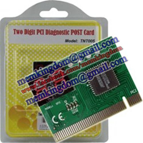
Product Name: Two Digit PCI Diagnostic Card (entry series)
Price: RM54.00
Product Specification:
► BIOS POST (Power On Self Test) Diagnotic Card For PCI Slot
► Two Digit POST Code Panel
█ Powerful Diagnostic Tool For Technician & Engineer To Troubleshoot Various Problem Of Mother Board

Product Name: Four Digit PCI Diagnostic Card (upgraded series)
Price: RM74.00
Product Specification:
► BIOS POST (Power On Self Test) Diagnotic Card For PCI Slot
► Four Digit POST Code Panel (Two Digit Current Code + Two Digit Previous Code)
█ Powerful Diagnostic Tool For Technician & Engineer To Troubleshoot Various Problem Of Mother Board
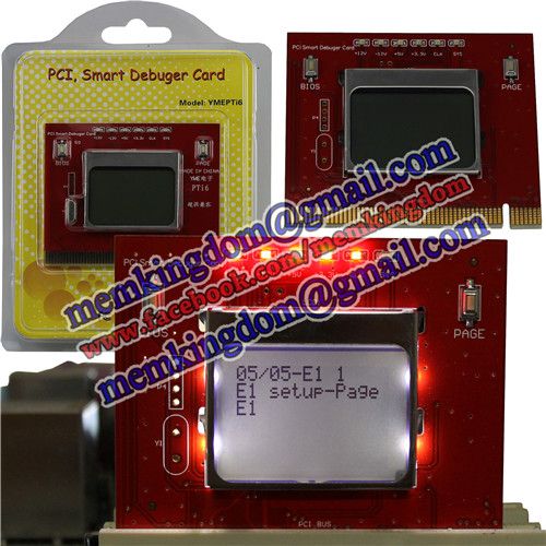
Product Name: PCI Diagnotic POST Card With LCD Screen
Price: RM144.00
Product Specification:
► BIOS POST (Power On Self Test) Diagnotic Card For PCI Slot
► LCD Screen Display Error Code
█ Powerful Diagnostic Tool For Technician & Engineer To Troubleshoot Various Problem Of Mother Board
BIOS Beep Codes Analysis (May vary in different BIOS platform, just for your reference)
■1 Long Beep - POST has passed all tests
■1 Beep - DRAM Refresh Failure. Try reseating the memory first. If the error still occurs, replace the memory with known good chips.
■2 Beeps - Parity Error in First 64K RAM. Try reseating the memory first. If the error still occurs, replace the memory with known good chips.
■3 Beeps - Base 64K RAM Failure. Try reseating the memory first. If the error still occurs, replace the memory with known good chips.
■4 Beeps - System Timer #1 Failure
■5 Beeps - Processor Failure
■6 Beeps - Keyboard Controller 8042 - Gate A20 Error. try reseating the keyboard controller chip. If the error still occurs, replace the keyboard chip. If the error persists, check parts of the system relating to the keyboard, e.g. try another keyboard, check to see if the system has a keyboard fuse.
■7 Beeps - Processor Virtual Mode Exception Interrupt Error
■8 Beeps - Display Memory Read/Write Test Failure (Non-fatal). Replace the video card or the memory on the video card.
■9 Beeps - ROM BIOS Checksum (32KB at F800:0) Failed. It is not likely that this error can be corrected by reseating the chips. Consult the motherboard supplier or an AMI product distributor for replacement part(s).
■10 Beeps - CMOS Shutdown Register Read/Write Error
■11 Beeps - Cache Memory error
■1 Long, 2 Short - An error was encountered in the video BIOS ROM, or a horizontal retrace failure has been encountered
■1 Long, 3 Short - Conventional/Extended memory failure
■1 Long, 8 Short - Display/Retrace test failed
■2 Short - POST Failure - One or more of the hardware tests has failed
This post has been edited by memkingdom: Feb 1 2015, 06:20 PM
|
|
|
|
|
|
TSmemkingdom
|
Jul 24 2010, 08:43 AM
|
|
|
Notebook / Laptop Diagnostic Card (Notebook / Laptop Analyzer Card) (POST Card)
A MUST TOOLS for repairing mother board & PC trouble shooting. Ideal tools for Computer Engineer
Diagnostic Card is a powerful diagnostic tool for technicians and administrators to troubleshoot various problems of IBM compatible PCs. It is easy to install, yet extremely powerful to use. With Diagnostic Card in hand, you no longer have to go through tedious and time consuming process of trying to figure out what is wrong with your PC hardware. Diag nostic Card will tell you exactly what is wrong with your PC in just seconds. It saves you time and money. Our new and improved design of diagnostic card can work with almost all popular types of CPUs, Motherboards, and BIOS. All though we tr y, it is not possible to update this manual ever y time a new motherboard is made by
the manufactures. It is always advised to visit the bios manufacture website, and download the latest codes per bios revision. Or visit bioscentral.com for an online reference.
System Requirements
The Diagnostic Card itself only requires an empty Parallel Port / miniPCI / miniPCI-e expansion slot. It is not necessary to install
memory chips to perform analysis. “POST Codes” can be displayed through the hexadecimal
display panel on the Diagnostic Card itself.
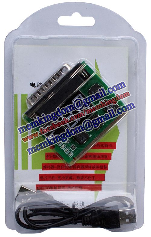
Product Name: Two Digit Parallel+MiniPCI Diagnostic POST Card
Price: RM44.00
Product Specification:
► BIOS POST (Power On Self Test) Diagnotic Card
► USB Powered Port (to Supply Power Only)
► DB25 Parallel Port (for Diagnostic Purpose)
► MiniPCI Slot (for Diagnostic Purpose)
► Two Digit POST Code Panel
█ Powerful Diagnostic Tool To Troubleshoot Various Problem Of Oldies Laptop / Notebook / Desktop Mother Board
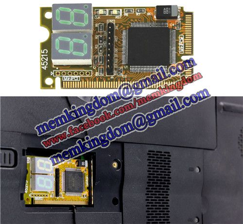
Product Name: mini PCI-e Diagnostic POST Card
Price: RM114.00
Product Specification:
► BIOS POST (Power On Self Test) Diagnotic Card
► Mini PCI Slot
► Mini PCI-E Slot
► Two Digit POST Code Panel
█ Powerful Diagnostic Tool To Troubleshoot Various Problem Of Newly Notebook Through mini PCI Slot / mini PCI-E Slot

Product Name: 31 in 1 Screw Set
Price: RM14.00
Product Specification:
► 30pcs Of Various Screw Blade
► 1pc Tweezer
► 1pc Handle
█ The Screwdriver Set Allows You To Open Small Electronics Like Laptop, LCD Monitor, Watch, EyeGlass & Etc
█ Small And Easy To Carry

Product Name: CR2032 CMOS Battery
Price: RM3.00 per piece
Product Specification:
► Lithium Battery
► Voltage: 3V
█ Use For Computer Mother Board, Calculator, Watch, Clock, Toy, Laser Pointer, LED Flashlight & Etc
AMI BIOS Code
01 NMI is disabled and the i286 register test is about to start
02 i286 register test has passed
03 ROM BIOS checksum test (32KB from E8000h) passed OK
04 Passed keyboard controller test with and without mouse
05 Chipset initialized...DMA and interrupt controller disabled
06 Video system disabled and the system timer checks OK
07 8254 programmable interval timer initialized
08 Delta counter channel 2 initialization complete
09 Delta counter channel 1 initialization complete
0A Delta counter channel 0 initialization complete
0B Refresh started
0C System timer started
0D Refresh check OK
10 Ready to start 64KB base memory test
11 Address line test OK
12 64KB base memory test OK
15 ISA BIOS interrupt vectors initialized
17 Monochrome video mode OK
18 CGA color mode set OK
19 Attempting to pass control to video ROM at C0000h
1A Returned from video ROM
1B Shadow RAM enabled
1C Display memory read/write test OK
1D Alternate display memory read/write test OK
1E Global equipment byte set for proper
1F Ready to initialize video system
20 Finished setting video mode
21 ROM type 27256 verified
22 The power-on message is displayed
30 Ready to start the virtual mode memory test
31 Virtual memory mode test started
32 CPU has switched to virtual mode
33 Testing the memory address lines
34 Testing the memory address lines
35 Lower 1MB of RAM found
36 Memory size computation checks OK
37 Memory test in progress
38 Memory below 1MB is initialized
39 Memory above 1MB is initialized
3A Memory size is displayed
3B Ready to test the lower 1MB of RAM
3C Memory test of lower 1MB OK
3D Memory test above 1MB OK
3E Ready to shutdown for real-mode testing
3F Shutdown Ok - now in real mode
40 Cache memory now on...Ready to disable gate A 20
41 A20 line disabled successfully
42 i486 internal cache turned on
43 Ready to start DMA controller test
50 DMA page register test OK
51 Starting DMA controller 1 register test
52 DMA controller 1 test passed, starting DMA controller 2 register test
53 DMA controller 2 test passed
54 Ready to test latch on DMA controller 1 and 2
55 DMA controller 1 and 2 latch test OK
56 DMA controller 1 and 2 configured OK
57 8259 programmable interrupt controller initialized Ok
70 Start of keyboard test
71 Keyboard controller OK
72 Keyboard test OK...Starting mouse interface test
73 Keyboard and mouse global initialization OK
74 Display setup prompt.. Floppy setup ready to start
75 Floppy controller setup OK
76 hard disk setup ready to start
77 Hard disk controller setup OK
79 Ready to initialize timer data
7A Timer data area initialized
7B CMOS battery verified OK
7E CMOS memory size updated
7F Enable setup routine if <Delete> is pressed
80 Send control to adapter ROM at C800h to DE00h
81 Return from adapter ROM
82 Printer data initialization is OK
83 RS-232 data initialization is OK
84 80x87 check and test OK
85 Display any soft error message
86 Give control to ROM at E0000h
A0 Program the cache SRAM
A1 Check for external cache
A2 initialize EISA adapter card slots
A3 Test extended NMI in EISA system
00 Call the INT19 boot loader
This post has been edited by memkingdom: Feb 1 2015, 06:30 PM
|
|
|
|
|
|
TSmemkingdom
|
Jul 24 2010, 08:43 AM
|
|
|
AWARD BIOS Code
■01 - Expand the Xgroup codes located in physical memory address 1000:0
■02 - Reserved
■03 - Initial Superio_Early_Init switch
■04 - Reserved
■05 - Blank out screen; Clear CMOS error flag
■06 - Reserved
■07 - Clear 8042 interface; Initialize 8042 self test
■08 - Test special keyboard controller for Winbond 977 series Super I/O chips; Enable keyboard interface
■09 - Reserved
■0A - Disable PS/2 mouse interface (optional); Auto detect ports for keyboard & mouse followed by a port & interface swap (optional); Reset keyboard for Winbond 977 series Super I/O chips
■0B - Reserved
■0C - Reserved
■0D - Reserved
■0E - Test F000h segment shadow to see whether it is read/write capable or not. If test fails, keep beeping the speaker
■0F - Reserved
■10 - Auto detect flash type to load appropriate flash read/write codes into the run time area in F000 for ESCD & DMI support
■11 - Reserved
■12 - Use walking 1's algorithm to check out interface in CMOS circuitry. Also set real time clock power status and then check for overrride
■13 - Reserved
■14 - Program chipset default values into chipset. Chipset default values are MODBINable by OEM customers
■15 - Reserved
■16 - Initial Early_Init_Onboard_Generator switch
■17 - Reserved
■18 - Detect CPU information including brand, SMI type (Cyrix or Intel) and CPU level (586 or 686)
■19 - Reserved
■1A - Reserved
■1B - Initial interrupts vector table. If no special specified, all H/W interrupts are directed to SPURIOUS_INT_HDLR & S/W interrupts to SPURIOUS_soft_HDLR
■1C - Reserved
■1D - Initial EARLY_PM_INIT switch
■1E - Reserved
■1F - Load keyboard matrix (notebook platform)
■20 - Reserved
■21 - HPM initialization (notebook platform)
■22 - Reserved
■23 - Check validity of RTC value; Load CMOS settings into BIOS stack. If CMOS checksum fails, use default value instead; Prepare BIOS resource map for PCI & PnP use. If ESCD is valid, take into consideration of the ESCD's legacy information; Onboard clock generator initialization. Disable respective clock resource to empty PCI & DIMM slots; Early PCI initialization - Enumerate PCI bus number, assign memory & I/O resource, search for a valid VGA device & VGA BIOS, and put it into C000:0
■24 - Reserved
■25 - Reserved
■26 - Reserved
■27 - Initialize INT 09 buffer
■28 - Reserved
■29 - Program CPU internal MTRR (P6 & PII) for 0-640K memory address; Initialize the APIC for Pentium class CPU; Program early chipset according to CMOS setup; Measure CPU speed; Invoke video BIOS
■2A - Reserved
■2B - Reserved
■2C - Reserved
■2D - Initialize multilanguage; Put information on screen display, including Award title, CPU type, CPU speed, etc...
■2E - Reserved
■2F - Reserved
■30 - Reserved
■31 - Reserved
■32 - Reserved
■33 - Reset keyboard except Winbond 977 series Super I/O chips
■34 - Reserved
■35 - Reserved
■36 - Reserved
■37 - Reserved
■38 - Reserved
■39 - Reserved
■3A - Reserved
■3B - Reserved
■3C - Test 8254
■3D - Reserved
■3E - Test 8259 interrupt mask bits for channel 1
■3F - Reserved
■40 - Test 9259 interrupt mask bits for channel 2
■41 - Reserved
■42 - Reserved
■43 - Test 8259 functionality
■44 - Reserved
■45 - Reserved
■46 - Reserved
■47 - Initialize EISA slot
■48 - Reserved
■49 - Calculate total memory by testing the last double last word of each 64K page; Program writes allocation for AMD K5 CPU
■4A - Reserved
■4B - Reserved
■4C - Reserved
■4D - Reserved
■4E - Program MTRR of M1 CPU; initialize L2 cache for P6 class CPU & program cacheable range; Initialize the APIC for P6 class CPU; On MP platform, adjust the cacheable range to smaller one in case the cacheable ranges between each CPU are not identical
■4F - reserved
■50 - Initialize USB
■51 - Reserved
■52 - Test all memory (clear all extended memory to 0)
■53 - Reserved
■54 - Reserved
■55 - Display number of processors (multi-processor platform)
■56 - Reserved
■57 - Display PnP logo; Early ISA PnP initialization and assign CSN to every ISA PnP device
■58 - Reserved
■59 - Initialize the combined Trend Anti-Virus code
■5A - Reserved
■5B - Show message for entering AWDFLASH.EXE from FDD (optional feature)
■5C - Reserved
■5D - Initialize Init_Onboard_Super_IO switch; Initialize Init_Onboard_AUDIO switch
■5E - Reserved
■5F - Reserved
■60 - Okay to enter Setup utility
■61 - Reserved
■62 - Reserved
■63 - Reserved
■64 - Reserved
■65 - Initialize PS/2 mouse
■66 - Reserved
■67 - Prepare memory size information for function call: INT 15h ax=E820h
■68 - Reserved
■69 - Turn on L2 cache
■6A - Reserved
■6B - Program chipset registers according to items described in Setup & Auto-Configuration table
■6C - Reserved
■6D - Assign resources to all ISA PnP devices; Auto assign ports to onboard COM ports if the corresponding item in Setup is set to 'AUTO'
■6E - Reserved
■6F - Initialize floppy controller; Setup floppy related fields in 40:hardware
■70 - Reserved
■71 - Reserved
■72 - Reserved
■73 - Enter AWDFLASH.EXE if: AWDFLASH.EXE is found in floppy dive and ALT+F2 is pressed
■74 - Reserved
■75 - Detect and install all IDE devices: HDD, LS120, ZIP, CDROM...
■76 - Reserved
■77 - Detect serial ports and parallel ports
■78 - Reserved
■79 - Reserved
■7A - Detect and install coprocessor
■7B - Reserved
■7C - Reserved
■7D - Reserved
■7E - Reserved
■7F - Switch back to text mode if full screen logo is supported: if errors occur, report errors & wait for keys, if no errors occur or F1 key is pressed continue - Clear EPA or customization logo
■80 - Reserved
■81 - Reserved
■82 - Call chipset power management hook: Recover the text fond used by EPA logo (not for full screen logo), If password is set, ask for password
■83 - Save all data in stack back to CMOS
■84 - Initialize ISA PnP boot devices
■85 - Final USB initialization; NET PC: Build SYSID structure; Switch screen back to text mode; Set up ACPI table at top of memory; Invoke ISA adapter ROM's; Assign IRQ's to PCI devices; Initialize APM; Clear noise of IRQ's
■86 - Reserved
■87 - Reserved
■88 - Reserved
■89 - Reserved
■90 - Reserved
■91 - Reserved
■92 - Reserved
■93 - Read HDD boot sector information for Trend Anti-Virus code
■94 - Enable L2 cache; Program boot up speed; Chipset final initialization; Power management final initialization; Clear screen and display summary table; Program K^ write allocation; Program P6 class write combining
■95 - Program daylight saving; Update keyboard LED and typematic rate
■96 - Build MP table; Build and update ESCD; Set CMOS century to 20h or 19h; Load CMOS time into DOS timer tick; Build MSIRQ routing table
■C0 - Early chipset initialization: Disable shadow RAM, L2 cache (socket 7 and below), program basic chipset registers
■C1 - Detect memory: Auto detection of DRAM size, type and ECC, auto detection of L2 cache (socket 7 and below)
■C3 - Expand compressed BIOS code to DRAM
■C5 - Call chipset hook to copy BIOS back to E000 & F000 shadow RAM
■CF - Test CMOS read/write functionality
■FF - Boot attempt (INT 19h)
This post has been edited by memkingdom: Jul 24 2010, 08:53 AM
|
|
|
|
|
|
TSmemkingdom
|
Jul 24 2010, 08:45 AM
|
|
|
PHOENIX BIOS CODE
■Note - If the BIOS detects error 2C, 2E, or 30 (base 512K RAM error), it displays an additional word-bitmap (xxxx) indicating the address line or bits that failed. For example, '2C 0002' means address line 1 (bit one set) has failed. '2E 1020' means data bits 12 and 5 (bits 12 and 5 set) have failed in the lower 16 bits. Note that error 30 cannot occur on 386SX systems because they have a 16 rather than 32-bit bus. The BIOS also sends the bitmap to the port-80 LED display. It first displays the checkpoint code, followed by a delay, the high-order byte, another delay, and then the low-order byte of the error. It repeats this sequence continuously.
■02 - Verify Real Mode
■03 - Disable Non-Maskable Interrupt (NMI)
■04 - Get CPU type
■06 - Initialize system hardware
■07 - Disable shadow and execute code from the ROM.
■08 - Initialize chipset with initial POST values
■09 - Set IN POST flag
■0A - Initialize CPU registers
■0B - Enable CPU cache
■0C - Initialize caches to initial POST values
■0E - Initialize I/O component
■0F - Initialize the local bus IDE
■10 - Initialize Power Management
■11 - Load alternate registers with initial POST values
■12 - Restore CPU control word during warm boot
■13 - Initialize PCI Bus Mastering devices
■14 - Initialize keyboard controller
■16 - BIOS ROM checksum
■17 - Initialize cache before memory Auto size
■18 - 8254 timer initialization
■1A - 8237 DMA controller initialization
■1C - Reset Programmable Interrupt Controller
■20 - Test DRAM refresh
■22 - Test 8742 Keyboard Controller
■24 - Set ES segment register to 4 GB
■28 - Auto size DRAM
■29 - Initialize POST Memory Manager
■2A - Clear 512 kB base RAM
■2C - RAM failure on address line xxxx*
■2E - RAM failure on data bits xxxx* of low byte of memory bus
■2F - Enable cache before system BIOS shadow
■32 - Test CPU bus-clock frequency
■33 - Initialize Phoenix Dispatch Manager
■36 - Warm start shut down
■38 - Shadow system BIOS ROM
■3A - Auto size cache
■3C - Advanced configuration of chipset registers
■3D - Load alternate registers with CMOS values
■41 - Initialize extended memory for RomPilot
■42 - Initialize interrupt vectors
■45 - POST device initialization
■46 - Check ROM copyright notice
■47 - Initialize I20 support
■48 - Check video configuration against CMOS
■49 - Initialize PCI bus and devices
■4A - Initialize all video adapters in system
■4B - QuietBoot start (optional)
■4C - Shadow video BIOS ROM
■4E - Display BIOS copyright notice
■4F - Initialize MultiBoot
■50 - Display CPU type and speed
■51 - Initialize EISA board
■52 - Test keyboard
■54 - Set key click if enabled
■55 - Enable USB devices
■58 - Test for unexpected interrupts
■59 - Initialize POST display service
■5A - Display prompt 'Press F2 to enter SETUP'
■5B - Disable CPU cache
■5C - Test RAM between 512 and 640 kB
■60 - Test extended memory
■62 - Test extended memory address lines
■64 - Jump to UserPatch1
■66 - Configure advanced cache registers
■67 - Initialize Multi Processor APIC
■68 - Enable external and CPU caches
■69 - Setup System Management Mode (SMM) area
■6A - Display external L2 cache size
■6B - Load custom defaults (optional)
■6C - Display shadow-area message
■6E - Display possible high address for UMB recovery
■70 - Display error messages
■72 - Check for configuration errors
■76 - Check for keyboard errors
■7C - Set up hardware interrupt vectors
■7D - Initialize Intelligent System Monitoring
■7E - Initialize coprocessor if present
■80 - Disable onboard Super I/O ports and IRQs
■81 - Late POST device initialization
■82 - Detect and install external RS232 ports
■83 - Configure non-MCD IDE controllers
■84 - Detect and install external parallel ports
■85 - Initialize PC-compatible PnP ISA devices
■86 - Re-initialize onboard I/O ports.
■87 - Configure Motherboard Configurable Devices (optional)
■88 - Initialize BIOS Data Area
■89 - Enable Non-Maskable Interrupts (NMIs)
■8A - Initialize Extended BIOS Data Area
■8B - Test and initialize PS/2 mouse
■8C - Initialize floppy controller
■8F - Determine number of ATA drives (optional)
■90 - Initialize hard-disk controllers
■91 - Initialize local-bus hard-disk controllers
■92 - Jump to UserPatch2
■93 - Build MPTABLE for multi-processor boards
■95 - Install CD ROM for boot
■96 - Clear huge ES segment register
■97 - Fix up Multi Processor table
■98 - Search for option ROMs. One long, two short beeps on checksum failure
■99 - Check for SMART Drive (optional)
■9A - Shadow option ROMs
■9C - Set up Power Management
■9D - Initialize security engine (optional)
■9E - Enable hardware interrupts
■9F - Determine number of ATA and SCSI drives
■A0 - Set time of day
■A2 - Check key lock
■A4 - Initialize typematic rate
■A8 - Erase F2 prompt
■AA - Scan for F2 key stroke
■AC - Enter SETUP
■AE - Clear Boot flag
■B0 - Check for errors
■B1 - Inform RomPilot about the end of POST.
■B2 - POST done - prepare to boot operating system
■B4 - 1 One short beep before boot
■B5 - Terminate QuietBoot (optional)
■B6 - Check password (optional)
■B7 - Initialize ACPI BIOS
■B9 - Prepare Boot
■BA - Initialize SMBIOS
■BB - Initialize PnP Option ROMs
■BC - Clear parity checkers
■BD - Display MultiBoot menu
■BE - Clear screen (optional)
■BF - Check virus and backup reminders
■C0 - Try to boot with INT 19
■C1 - Initialize POST Error Manager (PEM)
■C2 - Initialize error logging
■C3 - Initialize error display function
■C4 - Initialize system error handler
■C5 - PnPnd dual CMOS (optional)
■C6 - Initialize note dock (optional)
■C7 - Initialize note dock late
■C8 - Force check (optional)
■C9 - Extended checksum (optional)
■CA - Redirect Int 15h to enable remote keyboard
■CB - Redirect Int 13h to Memory Technologies Devices such as ROM, RAM, PCMCIA, and serial disk
■CC - Redirect Int 10h to enable remote serial video
■CD - Re-map I/O and memory for PCMCIA
■CE - Initialize digitizer and display message
■D2 - Unknown interrupt
■E0 - Initialize the chipset
■E1 - Initialize the bridge
■E2 - Initialize the CPU
■E3 - Initialize system timer
■E4 - Initialize system I/O
■E5 - Check force recovery boot
■E6 - Checksum BIOS ROM
■E7 - Go to BIOS
■E8 - Set Huge Segment
■E9 - Initialize Multi Processor
■EA - Initialize OEM special code
■EB - Initialize PIC and DMA
■EC - Initialize Memory type
■ED - Initialize Memory size
■EE - Shadow Boot Block
■EF - System memory test
■F0 - Initialize interrupt vectors
■F1 - Initialize Run Time Clock
■F2 - Initialize video
■F3 - Initialize System Management Manager
■F4 - Output one beep
■F5 - Clear Huge Segment
■F6 - Boot to Mini DOS
■F7 - Boot to Full DOS
This post has been edited by memkingdom: Jul 24 2010, 08:55 AM
|
|
|
|
|
|
k3lvinng007
|
Jul 24 2010, 08:50 AM
|
|
|
wow..sound very usefull...got pic???or any review?
|
|
|
|
|
|
TSmemkingdom
|
Jul 24 2010, 08:57 AM
|
|
|
QUOTE(k3lvinng007 @ Jul 24 2010, 08:50 AM) wow..sound very usefull...got pic???or any review? I Still doing posting of product description, will upload product photo today later. Just give me some time, so much thing need to upload, very messy & busy  |
|
|
|
|
|
TSmemkingdom
|
Jul 24 2010, 10:19 AM
|
|
|
QUOTE(k3lvinng007 @ Jul 24 2010, 08:50 AM) wow..sound very usefull...got pic???or any review? Picture uploaded  Please had a view  |
|
|
|
|
|
ktek
|
Aug 11 2010, 07:50 PM
|
|
|
this got power/reset button one?
|
|
|
|
|
|
TSmemkingdom
|
Aug 11 2010, 08:16 PM
|
|
|
QUOTE(ktek @ Aug 11 2010, 07:50 PM) this got power/reset button one? Power & Reset button??? PCI Diagnostic Card dont had Power Button  What use for having those two function ?  |
|
|
|
|
|
saoirse
|
Aug 25 2010, 09:33 PM
|
Getting Started

|
what is the difference with entry, 2digit and upgraded,4digit card?
|
|
|
|
|
|
TSmemkingdom
|
Aug 25 2010, 11:42 PM
|
|
|
QUOTE(saoirse @ Aug 25 2010, 09:33 PM) what is the difference with entry, 2digit and upgraded,4digit card? 4digit is advance version card. first 2digit appear current process, another 2digit appear previous process, that could help you easy to find out what it's done before hang-up. |
|
|
|
|
|
helangkawi
|
Sep 7 2010, 02:07 PM
|
|
|
pci diagnostic card and psu tester, bundle together best price please
and also where can cod
|
|
|
|
|
|
Jackygwh
|
Sep 17 2010, 07:20 PM
|
|
|
bro u got stock for 4 digit one ? best price how much to kuching ?
|
|
|
|
|
|
TSmemkingdom
|
Sep 17 2010, 07:35 PM
|
|
|
QUOTE(Jackygwh @ Sep 17 2010, 07:20 PM) bro u got stock for 4 digit one ? best price how much to kuching ? Yes, got stock for both version |
|
|
|
|
|
saoirse
|
Sep 20 2010, 08:06 PM
|
Getting Started
|
how much if i buy the psu tester and 4digit PCI?with free postage?
|
|
|
|
|
|
TSmemkingdom
|
Sep 20 2010, 09:38 PM
|
|
|
QUOTE(saoirse @ Sep 20 2010, 08:06 PM) how much if i buy the psu tester and 4digit PCI?with free postage? OK, if you buy two item together, I can free courier to you.  |
|
|
|
|
|
cincaluk
|
Dec 22 2010, 04:31 PM
|
New Member
|
bro,
pm price for two digit + postage to seremban.
thx
|
|
|
|
|
|
TSmemkingdom
|
Dec 22 2010, 04:52 PM
|
|
|
QUOTE(cincaluk @ Dec 22 2010, 04:31 PM) bro, pm price for two digit + postage to seremban. thx OK, done.  |
|
|
|
|
|
ARe-BeaR
|
Mar 13 2011, 03:45 PM
|
New Member
|
pci diagnostic card (4digit) and psu tester, bundle together best price please pm me...
|
|
|
|
|


 Quote
Quote


 0.0259sec
 0.37
0.37
 5 queries
 GZIP Disabled