

 Mar 2 2008, 10:49 AM

QUOTE(lienster @ Mar 1 2008, 07:29 AM)
 understand cam 1st; then can understand how cam pulley work to get back ideal ignition point
There is only one way to increase the performance of an engine, and that is to cram more fuel/air mixture into the cylinder, compress it and then ignite it. The bigger the bang, the more energy is released and if this energy is efficiently harnessed the higher the performance of the engine.
Many ways are employed to fill the cylinders, such as high flow air filters, multi carburettors, big ass fuel Injetcors, ported and large valve cylinder heads, supercharging and turbocharging.. However no matter what methods are used they all rely on the camshaft opening the valves high enough and long enough to enable them to get this increased mixture into the engine.
It is the enhanced "lift" and "duration" that is imparted to the valves by the high performance camshaft, that makes it an altogether different component to the standard cam. It is usually these figures that are the measure of how "hot" or radical the performance cam is.
High performance cams are often surrounded by a good deal of mysticism, confusion and ignorance, largely brought about by the lack of reliable information from the performance cam manufacturer. It is the intention of this publication to inform, and to make cam selection easy to understand.
The function of the camshaft is to lift the valve off the seat, and, as it rotates, to allow the valve spring to close it again. There are numerous ways in which engine designers have linked the camshaft to the valve, but the most common are -
Push rod and rocker arm e.g. GM V8 blocks :monkey:
Finger follower e.g. Astra "J" and Ford
Each method of linking the cam to the valve, or valve train, requires a different design of cam profile. possible to select a,push rod profile for a direct acting application, or vice versa. of the engine.
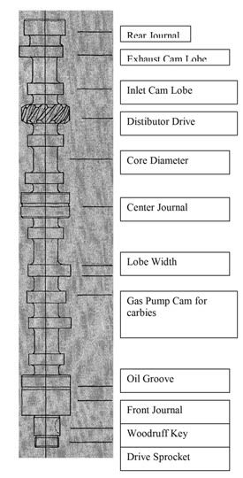
Figure of a camshaft
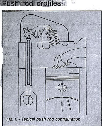
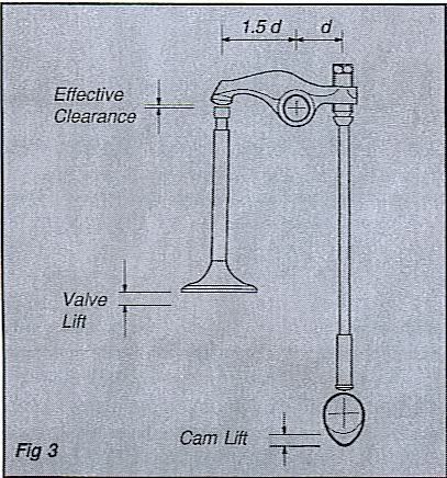
Generally speaking all push rod engine profiles have less cam lift than valve lift. The rocker arm has an offset pivot rather like a lever, and as the push rod activates the arm, this motion is multiplied, by the amount of offset of the pivot, and transmitted to the valve. This offset is usually refered to as a ratio, and is normally in the region of 1.5:1. This means for every .010" of cam lift, the valve will open .015" i.e.. cam lift .010." x rocker ratio 1.5 = .015" valve lift. (see fig 3)
However it must be remembered when calculating valve lift, that.all mechanical profiles operate with a valve clearance and this clearance must be deducted from the total lift in order to find the true valve lift. e.g.. Cam lift .200" x rocker ratio 1.5 = .300" - clearance .010" = valve lift .290" (see fig 3)
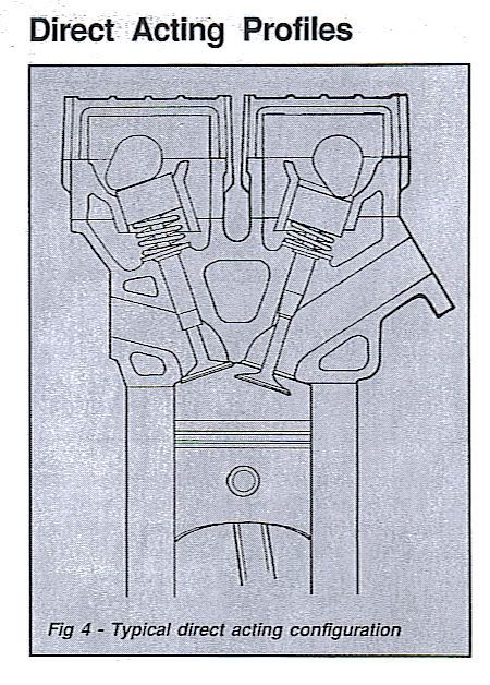
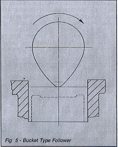
This is probably the easiest of all valve trains to understand as the cam operates directly onto a bucket type follower, (so called as it looks rather like an inverted bucket. See fig 5) and the cam motion is transmitted via an adjustment shim to the valve. Because of the relatively compact area of this type of design it is invariably used in twin-cam applications.(fig 4)
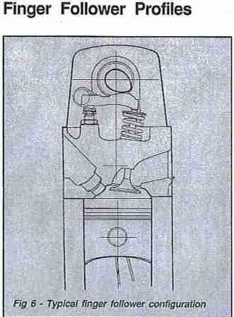
The vast majority of finger follower type profiles utilise an asymmetric cam profile operating on a radiused finger. (see fig.5) The finger is pivoted at one end on an adjustable ball stud and the cam operates on a radiused pad on the finger and this motion is then transmitted to the other end of the finger where it operates the valve. The finger is designed in very much the same way as the push rod rocker arm. i.e.. it also employs a rocker ratio, as the cam contact area is not in the centre of the finger. With some of the more radical race and rally profiles in Ford Pinto engines it has been found that the wipe area of the standard finger is too short and special long pad fingers are required. (part no CF12) Unlike both the push rod and direct acting set ups, there is a considerable wipe area of cam lobe over the finger, and fitting instructions must be adhered to if excessive wear to both the cam and fingers is to be avoided.

 Quote
Quote 0.0430sec
 0.90
0.90
 6 queries
 GZIP Disabled