

as above title. whats the diff. roughly i know how the lighten 1 works. can some pls enlighten me on how the adjustable 1 works?
how an adjustable cam pulley works?
how an adjustable cam pulley works?
|
|
 Feb 28 2008, 10:58 PM, updated 18y ago Feb 28 2008, 10:58 PM, updated 18y ago
Show posts by this member only | Post
#1
|

Staff
4,380 posts Joined: Mar 2005 From: petaling jaya,puchong jaya,pandan jaya,putra jaya |
as above title. whats the diff. roughly i know how the lighten 1 works. can some pls enlighten me on how the adjustable 1 works?
|
|
|
|
|
|
Feb 28 2008, 11:38 PM
Show posts by this member only | Post
#2
|

Senior Member
664 posts Joined: Jan 2003 From: Cheras, KL |
err, i think u got confused with CAM PULLEY and CRANK PULLEY
|
|
|
Feb 29 2008, 12:30 AM
Show posts by this member only | Post
#3
|
|
Senior Member
10,975 posts Joined: Jan 2003 From: disini disana |
there isnt any adjustable crankpulley available...
campulley is the top one... crankpulley is the bottom one... there is adjustable campulley and lightened crankpulley... both different thing... |
|
|
Feb 29 2008, 12:37 AM
Show posts by this member only | Post
#4
|

All Stars
15,278 posts Joined: Jan 2003 |
lol if adjustable crank pulley then easier to put supercharger XD
|
|
|
Feb 29 2008, 01:16 AM
Show posts by this member only | Post
#5
|
|
Staff
4,380 posts Joined: Mar 2005 From: petaling jaya,puchong jaya,pandan jaya,putra jaya |
ooooo. crank is the 1 at the bottom? okie okie. so how a adjustable cam pulley works then?
|
|
|
Feb 29 2008, 02:31 AM
Show posts by this member only | Post
#6
|
|
Senior Member
10,975 posts Joined: Jan 2003 From: disini disana |
QUOTE(scotty @ Feb 29 2008, 01:16 AM) ooooo. crank is the 1 at the bottom? okie okie. so how a adjustable cam pulley works then? it allows u to retard or advance the timing of ur car...  |
|
|
|
|
|
Feb 29 2008, 02:47 AM
Show posts by this member only | Post
#7
|
|
Staff
4,380 posts Joined: Mar 2005 From: petaling jaya,puchong jaya,pandan jaya,putra jaya |
QUOTE(the_catacombs @ Feb 29 2008, 02:31 AM) it allows u to retard or advance the timing of ur car... i read somewhere, advance means inlet valve comes down faster than normal first then only the piston comes up? sorry noob here.  |
|
|
Feb 29 2008, 09:58 AM
Show posts by this member only | Post
#8
|

Senior Member
3,945 posts Joined: Jan 2003 |
so retard and advance what we gain then? got any sifu can explaint. me noobie
|
|
|
Feb 29 2008, 10:08 AM
Show posts by this member only | Post
#9
|
|
Senior Member
3,872 posts Joined: Jan 2003 From: 10001011010101 |
Retard and advance means you... actually, screw that. it's way too technical for me to explain. Let's just say that by retarding or advancing the valve openings you get to fine-tune the amount of air going into the petrol chamber. More, or less, to optimize the compression - AKA increase/decrease the power.
Basically, it lets you choose to burn rich (too much petrol, too little air) or burn lean (too little petrol, too much air). Most cars are tuned to burn rich, which produces less power. But tune it too lean and you risk knocking or worse, detonation. |
|
|
Feb 29 2008, 01:47 PM
|

Senior Member
3,772 posts Joined: Jan 2003 |
If i am not mistaken the adjustable cam pulley allows adjustment of valve timing as mentioned above.
At low engine speed you would want the intake valve to open slightly before the exhaust valve close totally to take advantage of the vacuum caused by the exiting exhaust to pull more air and fuel in. At high speed the intake should open AFTER the exhaust closes because if they overlap, the incoming air and fuel will go straight out the exhaust because it's moving at much higher speed causing loss of power. So you can adjust the valve timings to suit what you are looking for. BUT you ask 'then isn't that only one setting?' Exactly! so welcome to the age of VVTi,i-VTEC,VANOS,CVVT,DVVT,MIVEC, variable valve timing. Variable valve timing now allows the engine to adjust itself the best conditions for every engine speed. |
|
|
Feb 29 2008, 03:41 PM
|
|
Senior Member
10,975 posts Joined: Jan 2003 From: disini disana |
QUOTE(lonewolf @ Feb 29 2008, 09:58 AM) so retard and advance what we gain then? got any sifu can explaint. me noobie retard to gain more top end power... advance to gain more initial pickup acceleration....retard more u gain more top speed.... but cannot retard too much or else initial acceleration will be jerky.... advance more u gain better initial pickup... but over advanced will cause detonation, which is bad for engine... |
|
|
Mar 1 2008, 12:20 AM
|

Senior Member
1,008 posts Joined: Jan 2005 From: Shah Alam SDE |
for what i know, by adjusting ur distributer 1degree weather clockwise/anti-clockwise also can make it retard/advance (but if got distributer la)....
i think when using adjustable campulley can make it more retard/advance to higher level.... but using programable ECU also can done that without adjusting campulley, but dunno which one more accurate? |
|
|
Mar 1 2008, 01:36 AM
|

Senior Member
936 posts Joined: Jun 2005 |
ecu can only adjust the ignition timing for normal engines. for those with vvt or some form of it you can adjust when it happens but not how much.
there are 3 reasons why adjustable pulleys are used. 1 - They just look cool when exposed don't they ? 2 - For engines with out vvt or some form of it, you cannot adjust the cam timing with the standard pulley. 3 - For track guys you will know this. Officially speaking, vvt is something like turbocharging so when on the track there is a weight penalty for cars wif vvt. Thats why the track engines have the vtec disabled or the vvt oil hole plugged. Don't get mixed up with the ignition timing and the cam timing. Ignition timing is to adjust when the spark plug fires relative to piston position cam timing is to control when the valve opens relative to piston position. Added on March 1, 2008, 1:38 amalso, the adjusting is actually to suit different the user. If you use the engine mainly at low rpms then less overlap is better. if you are at high rpms more overlap is better. overlap is the amount of time the intake valve is open while the exhaust valve is open. This post has been edited by sakaic: Mar 1 2008, 01:38 AM |
|
|
|
|
|
Mar 1 2008, 07:29 AM
|

Junior Member
160 posts Joined: Jan 2007 From: kl |
 understand cam 1st; then can understand how cam pulley work to get back ideal ignition point understand cam 1st; then can understand how cam pulley work to get back ideal ignition pointThere is only one way to increase the performance of an engine, and that is to cram more fuel/air mixture into the cylinder, compress it and then ignite it. The bigger the bang, the more energy is released and if this energy is efficiently harnessed the higher the performance of the engine. Many ways are employed to fill the cylinders, such as high flow air filters, multi carburettors, big ass fuel Injetcors, ported and large valve cylinder heads, supercharging and turbocharging.. However no matter what methods are used they all rely on the camshaft opening the valves high enough and long enough to enable them to get this increased mixture into the engine. It is the enhanced "lift" and "duration" that is imparted to the valves by the high performance camshaft, that makes it an altogether different component to the standard cam. It is usually these figures that are the measure of how "hot" or radical the performance cam is. High performance cams are often surrounded by a good deal of mysticism, confusion and ignorance, largely brought about by the lack of reliable information from the performance cam manufacturer. It is the intention of this publication to inform, and to make cam selection easy to understand. The function of the camshaft is to lift the valve off the seat, and, as it rotates, to allow the valve spring to close it again. There are numerous ways in which engine designers have linked the camshaft to the valve, but the most common are - Push rod and rocker arm e.g. GM V8 blocks :monkey: Finger follower e.g. Astra "J" and Ford Each method of linking the cam to the valve, or valve train, requires a different design of cam profile. possible to select a,push rod profile for a direct acting application, or vice versa. of the engine. 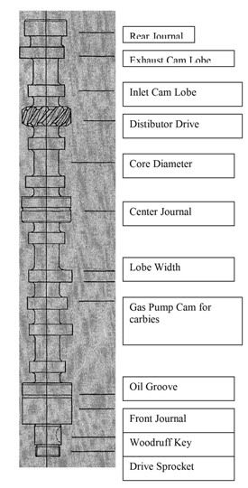 Figure of a camshaft 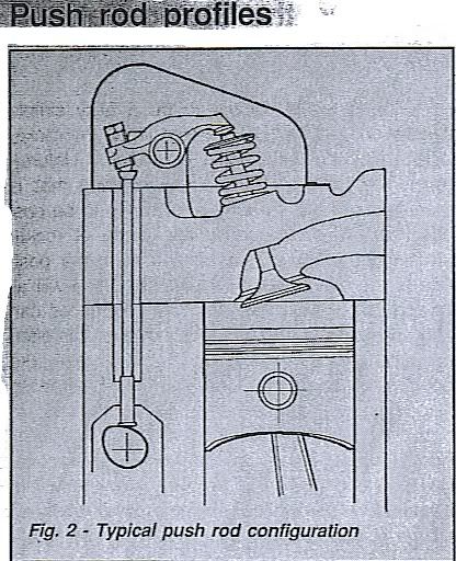 Generally speaking all push rod engine profiles have less cam lift than valve lift. The rocker arm has an offset pivot rather like a lever, and as the push rod activates the arm, this motion is multiplied, by the amount of offset of the pivot, and transmitted to the valve. This offset is usually refered to as a ratio, and is normally in the region of 1.5:1. This means for every .010" of cam lift, the valve will open .015" i.e.. cam lift .010." x rocker ratio 1.5 = .015" valve lift. (see fig 3) However it must be remembered when calculating valve lift, that.all mechanical profiles operate with a valve clearance and this clearance must be deducted from the total lift in order to find the true valve lift. e.g.. Cam lift .200" x rocker ratio 1.5 = .300" - clearance .010" = valve lift .290" (see fig 3) 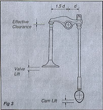 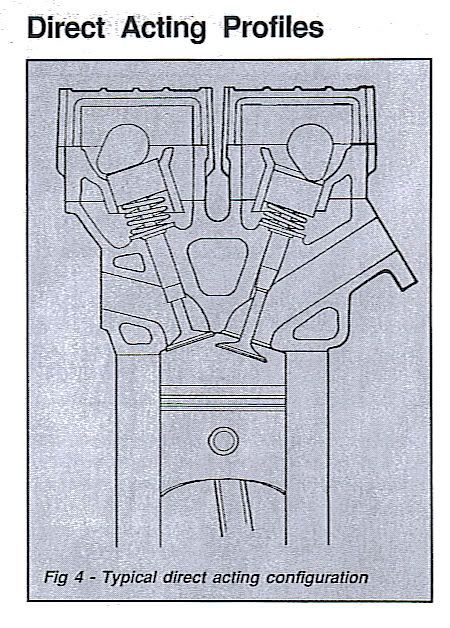 This is probably the easiest of all valve trains to understand as the cam operates directly onto a bucket type follower, (so called as it looks rather like an inverted bucket. See fig 5) and the cam motion is transmitted via an adjustment shim to the valve. Because of the relatively compact area of this type of design it is invariably used in twin-cam applications.(fig 4) 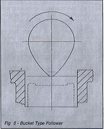 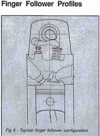 The vast majority of finger follower type profiles utilise an asymmetric cam profile operating on a radiused finger. (see fig.5) The finger is pivoted at one end on an adjustable ball stud and the cam operates on a radiused pad on the finger and this motion is then transmitted to the other end of the finger where it operates the valve. The finger is designed in very much the same way as the push rod rocker arm. i.e.. it also employs a rocker ratio, as the cam contact area is not in the centre of the finger. With some of the more radical race and rally profiles in Ford Pinto engines it has been found that the wipe area of the standard finger is too short and special long pad fingers are required. (part no CF12) Unlike both the push rod and direct acting set ups, there is a considerable wipe area of cam lobe over the finger, and fitting instructions must be adhered to if excessive wear to both the cam and fingers is to be avoided. This post has been edited by lienster: Mar 1 2008, 07:33 AM |
|
|
Mar 2 2008, 05:14 AM
|
|
Senior Member
10,975 posts Joined: Jan 2003 From: disini disana |
QUOTE(sakaic @ Mar 1 2008, 01:36 AM) 3 - For track guys you will know this. Officially speaking, vvt is something like turbocharging so when on the track there is a weight penalty for cars wif vvt. Thats why the track engines have the vtec disabled or the vvt oil hole plugged. i didnt know that...  QUOTE(lienster @ Mar 1 2008, 07:29 AM) » Click to show Spoiler - click again to hide... «  |
|
|
Mar 2 2008, 10:49 AM
|

Senior Member
6,724 posts Joined: Jan 2003 From: Seri Petaling |
QUOTE(lienster @ Mar 1 2008, 07:29 AM) understand cam 1st; then can understand how cam pulley work to get back ideal ignition pointThere is only one way to increase the performance of an engine, and that is to cram more fuel/air mixture into the cylinder, compress it and then ignite it. The bigger the bang, the more energy is released and if this energy is efficiently harnessed the higher the performance of the engine. Many ways are employed to fill the cylinders, such as high flow air filters, multi carburettors, big ass fuel Injetcors, ported and large valve cylinder heads, supercharging and turbocharging.. However no matter what methods are used they all rely on the camshaft opening the valves high enough and long enough to enable them to get this increased mixture into the engine. It is the enhanced "lift" and "duration" that is imparted to the valves by the high performance camshaft, that makes it an altogether different component to the standard cam. It is usually these figures that are the measure of how "hot" or radical the performance cam is. High performance cams are often surrounded by a good deal of mysticism, confusion and ignorance, largely brought about by the lack of reliable information from the performance cam manufacturer. It is the intention of this publication to inform, and to make cam selection easy to understand. The function of the camshaft is to lift the valve off the seat, and, as it rotates, to allow the valve spring to close it again. There are numerous ways in which engine designers have linked the camshaft to the valve, but the most common are - Push rod and rocker arm e.g. GM V8 blocks :monkey: Finger follower e.g. Astra "J" and Ford Each method of linking the cam to the valve, or valve train, requires a different design of cam profile. possible to select a,push rod profile for a direct acting application, or vice versa. of the engine. Figure of a camshaft Generally speaking all push rod engine profiles have less cam lift than valve lift. The rocker arm has an offset pivot rather like a lever, and as the push rod activates the arm, this motion is multiplied, by the amount of offset of the pivot, and transmitted to the valve. This offset is usually refered to as a ratio, and is normally in the region of 1.5:1. This means for every .010" of cam lift, the valve will open .015" i.e.. cam lift .010." x rocker ratio 1.5 = .015" valve lift. (see fig 3) However it must be remembered when calculating valve lift, that.all mechanical profiles operate with a valve clearance and this clearance must be deducted from the total lift in order to find the true valve lift. e.g.. Cam lift .200" x rocker ratio 1.5 = .300" - clearance .010" = valve lift .290" (see fig 3) This is probably the easiest of all valve trains to understand as the cam operates directly onto a bucket type follower, (so called as it looks rather like an inverted bucket. See fig 5) and the cam motion is transmitted via an adjustment shim to the valve. Because of the relatively compact area of this type of design it is invariably used in twin-cam applications.(fig 4) The vast majority of finger follower type profiles utilise an asymmetric cam profile operating on a radiused finger. (see fig.5) The finger is pivoted at one end on an adjustable ball stud and the cam operates on a radiused pad on the finger and this motion is then transmitted to the other end of the finger where it operates the valve. The finger is designed in very much the same way as the push rod rocker arm. i.e.. it also employs a rocker ratio, as the cam contact area is not in the centre of the finger. With some of the more radical race and rally profiles in Ford Pinto engines it has been found that the wipe area of the standard finger is too short and special long pad fingers are required. (part no CF12) Unlike both the push rod and direct acting set ups, there is a considerable wipe area of cam lobe over the finger, and fitting instructions must be adhered to if excessive wear to both the cam and fingers is to be avoided. |
|
|
Mar 2 2008, 05:18 PM
|
|
Junior Member
160 posts Joined: Jan 2007 From: kl |
Obtaining the Stated Valve Lift This would appear to be a fairly simple calculation, just multiply the cam lift by the rocker ratio and deduct the valve clearance. Unfortunately life isn't that simple. Everything that is manufactured has to have a tolerance to be cost effective and consequently the length of rocker arm, finger followers, valves and even the position of the ball studs in the cylinder head will all have small differences. All these differences can add up and work in our favour, however this often happens the other way round. This is really like good news and bad news, as these tolerances also allow us to juggle valves, rocker arms etc.. to obtain the optimum lift. It is worth noting that all quoted rocker ratios can only be a guide figure due to these variations, and are calculated from brand new unmodified engines using standard valves at a standard height relative to the rocker arms or fingers. Any variation of the valve height will alter this ratio. Generally speaking if the valve height is reduced the ratio will increase giving more valve lift, and conversely if the valve length is increased the ratio will decrease, resulting in less valve lift. (the effective valve length is increased each time the valve seats are recut) Cam Lobe Terminology We have seen the various methods in which the cam operates the valve, but regardless of how a particular valve train is configured, cam lobe design incorporates certain features common to all cases. 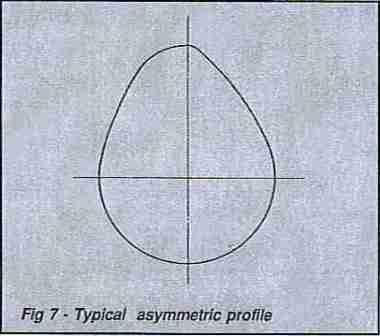 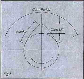 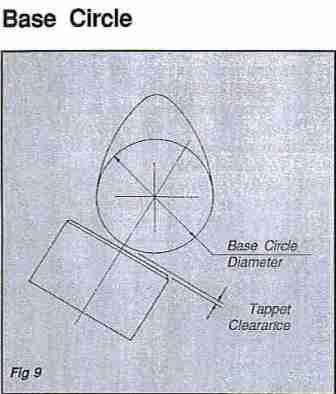 As you will see the base circle accounts for approx. 180 degrees of the cam profile and refers to the portion of the lobe that does not impart any valve motion as the cam rotates. It controls the part of the four stroke cycle where we require the valve to be closed. Theoretically the cam followers will not even run on this section of the lobe, as it is separated from it by valve clearance. (see fig. 9) Valve Clearances It is important to have some slack or clearance in the valve train to compensate for any expansion or growth of the components, due to heat generated when the engine reaches operating temperature. It is worth bearing in mind that any engine that produces more power will also produce more heat and this is why many performance cams run larger valve clearances than the standard or original cam, and are sometimes more noisy in operation. It is also common for the exhaust valve to run larger cold clearances than the inlet valve, because of its higher running temperature. However much depends on the design of the cylinder head and how efficient it is at dispersing the heat produced in the' combustion chamber, away from the valves. 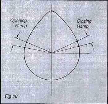 Ramp This is the section of the profile where the clearance is gently taken up as the cam rotates and prepares the cam follower to contact the cam lobe. Ramps are found both on the opening and closing side of the profile and in the case of the standard production cam, help to reduce valve train noise. However the ideal situation in a performance engine is to get the valve open as quickly as possible, and frequently these ramps are heavily modified, often making performance cams less quiet in operation. Obviously the design of the ramps have to be taken into account when designing performance profiles as an extremely noisy cam may be acceptable in a full race engine, but would be unacceptable in a mildly tuned family saloon. The closing ramp is usually less modified than the inlet on performance cams, as it is important to dose the valve gently back on its seat. If this is not the case, the valve will tend to crash back on its seat, and excessive damage to both valve and seat will result. Also the shock of this sudden collision can cause valve float, this being a situation where the valve will bounce back off its seat, thus opening the valve again just when we least want it. Flank The lobe flank is the section of the profile that extends from the ramp to the nose and it is this section of the profile that accelerates the cam follower to the full lift position. As the cam continues to rotate it allows the now compressed valve spring to close the valve in a controlled manner, until it rests back on its seat. The flank is a very important part of the performance profile as it controls the rate or acceleration of the valve. As we stated before, it is desirable in a high performance engine to open the valve as quickly as possible. However the flank has to take account of not only accelerating the whole mass of the valve train (valve, valve spring, valve retainers, push rods, cam followers etc..) but also has to start retarding it before the full lift position is reached. If this were not the case, the follower would no longer stay in contact with the lobe. We therefore only have approx. 50% of the flank to accelerate the whole mass of the valve train, and the further we try to open the valve, the more resistance the spring exerts to oppose it. So it can be seen that acceleration rates are a critical factor in performance cam design. Acceleration rates are limited by the diameter of the follower and it is easy to see why performance profiles are often on the limit of maximum acceleration, and why it is sensible to use the cam follower recommended by the manufacturer of the cam, as this will ensure that the design of the follower will be suitable for a particular profile, or range of profiles. With the need for a quick opening, and gentle closing of the valve, often the inlet and exhaust flank will have differing rates of acceleration, and with the very tight tolerances demanded of a performance profile, it soon becomes apparent that the engine must always be rotated in the correct direction. Quite apart from any damage caused by the backlash in the timing chain being reversed, there is also a chance of the cam lobe crashing with the edge of the followers. Always ensure that the engine is correctly set-up and that there is no possibility of pre-ignition as this may cause the engine to run in the opposite direction to which it was intended. This can result in broken cam followers, smashed lobes, bent valves, etc.. Nose The nose is the section of the profile where maximum lift occurs and is positioned each side of the opening and closing flanks. Due to differing cam design requirements and engine designs, the nose radii of performance cams can vary considerably. Some profiles look very pointed, whilst others may appear rounded. No matter what shape the profile may be the nose radius is the most highly stressed part of the profile, and the part that is most likely to fail. This section of the lobe has the least contact area with the followers, and at the same time has to overcome the full force of the valve spring, which is trying to prevent the valve opening. Pressure well in excess of 10,000 PSI, can be exerted on the lobe nose. It is therefore obvious that only the highest quality oils should be used in performance engines, when you consider that it is only the thin oil film separating the lobe and follower. If this film breaks down failure is inevitable. DWELL 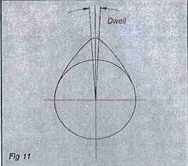 We have seen that the nose is the section of the profile where maximum lift occurs, but it is also the section of the profile that reverses the direction of the valve. We know that the cam lobe controls the opening and closing of the valve, but at some point the valve has to stop before it can reverse its direction. The length of time the valve remains at its maximum height (usually measured in degrees on the crankshaft) is called the dwell angle, and as we will see later, this dwell angle period is very important when setting up the cam. Lift and Duration As previously stated, the performance cam is generally judged by the advertised lift and duration figures, so it is important that we look closely at these two features. Lift When selecting a performance cam it is important to know how much lift a particular profile will impart to the valve. Generally speaking it is true to say the more lift a cam produces the more radical the profile, but also this information is essential in determining if the camshaft will fit in the engine without need to modify other components. When tuning any engine, it is common practice to increase the compression ratio, which means reducing the combustion chamber volume in relation to swept volume. This is often achieved by skimming the face of the cylinder head, thus reducing the clearances between piston and valves. Obviously if we increase the valve lift, we need to do some careful calculations to ensure that the valves do not contact the piston. It may be necessary to machine pockets in the piston crown. (see fig. 12) Whenever there is a possibility of valve to piston contact it is recommended that a trial engine build is carried out, using plasticine on top of the piston crowns. After rotating the engine it is then possible to measure the thickness of the plasticine and determine the valve to piston clearance. It is imperative that this clearance is not less than .060", otherwise the possibility of piston contact will result. 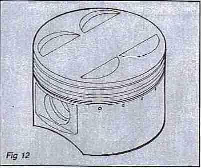 Cam lift can be calculated by deducting the base circle diameter from the overall lobe height. (see fig. 13) 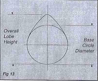 When measuring cam lift, it is impractical to use a micrometer to determine the base circle diameter, as it is not possible to see where the opening and closing ramps start and finish. If accurate results are to be achieved the cam lift must be measured between centres using a dial indicator gauge. When using this method the cam must be checked to ensure that it is not bent, that there is no run-out in the centres, the dial indicator is set up exactly on the centre line of the cam and at 90 degrees to the checking bed, before measuring. (see fig. 14) Never check cam lift in the engine as all the engine tolerances and clearances will combine to give inconsistent and unreliable information. 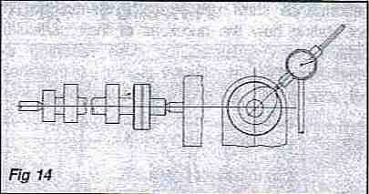 Many people find it difficult to understand that by grinding a lobe smaller, more lift can be achieved. This is probably best explained in fig. 15. 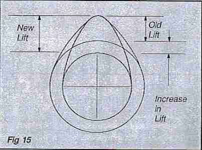 It is interesting to note that many performance cams have the core turned down. In general this is because when an existing cam is reprofiled, the base circle of the lobe is reduced to such an extent to obtain the greater lift, that it becomes smaller in diameter than the core, and if the core was not machined to a lesser diameter than that of the lobe, the cam follower would sit on the core and not the base circle of the cam. Also, even when using a new casting or blank, to obtain radical profiles the same situation often arises. This post has been edited by lienster: Mar 2 2008, 05:19 PM |
|
|
Mar 3 2008, 11:39 AM
|

Senior Member
1,017 posts Joined: Jan 2003 From: Malacca |
Mr. lienster, PLEASE quote your sources before flooding the thread with it. We wouldn't want LYN to be charged with plagiarism, now would we?
|
|
|
Mar 5 2008, 12:37 AM
|
|
Staff
4,380 posts Joined: Mar 2005 From: petaling jaya,puchong jaya,pandan jaya,putra jaya |
i just got the cam pulley. how many degrees would be ok?
  This post has been edited by scotty: Mar 5 2008, 03:07 AM |
|
|
Mar 5 2008, 02:31 AM
|
|
Senior Member
10,975 posts Joined: Jan 2003 From: disini disana |
QUOTE(scotty @ Mar 5 2008, 12:37 AM) i just got the cam pulley. how many degrees would ok? usually they will retard about 4 degree... but this vr vr much depends on ur tuning... get an experienced mech to get it tuned... even its not dyno tuned also nvm... my setting tuned by bawah pokok mech... so far vr satisfied.... » Click to show Spoiler - click again to hide... «  |
| Change to: |  0.0250sec 0.0250sec
 0.45 0.45
 5 queries 5 queries
 GZIP Disabled GZIP Disabled
Time is now: 21st December 2025 - 08:11 AM |
 Quote
Quote