

 Aug 2 2025, 10:03 AM, updated 3 months ago
Hi all,
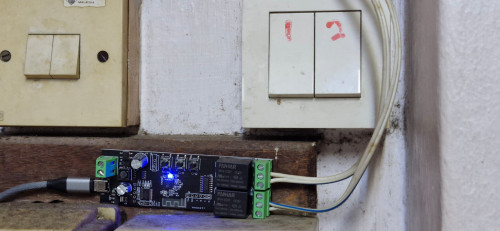
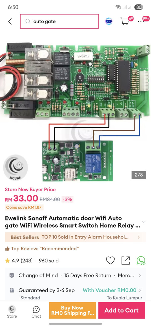
Currently I have this Sonoff MINIR4M. I need some clarification regarding compatibility with my autogate wall switch. Either this MINIR4M or Mini-D Dry Contact.
I am planning to use pulse mode, this relay will be in between my wall pushback switch (function - open/close gate) and the autogate. Mainly I am using this because it supports Apple Home. Those commonly used relay in the autogate box does not support Apple Home so its not an option for me. Does anyone know if this will work? My autogate is sliding gate and motor is CASA ASIA. I have done some research and some users have claimed it worked for them, but when I check with one electrician (to pull neutral wire), he keeps saying it will not work without justification. I will probably find another legit electrician for pulling the neutral wire.
This post has been edited by xkaizoku: Aug 2 2025, 10:06 AM
Sonoff Relay For Smart Autogate
 Quote
Quote


 0.0141sec
 0.29
0.29
 6 queries
 GZIP Disabled