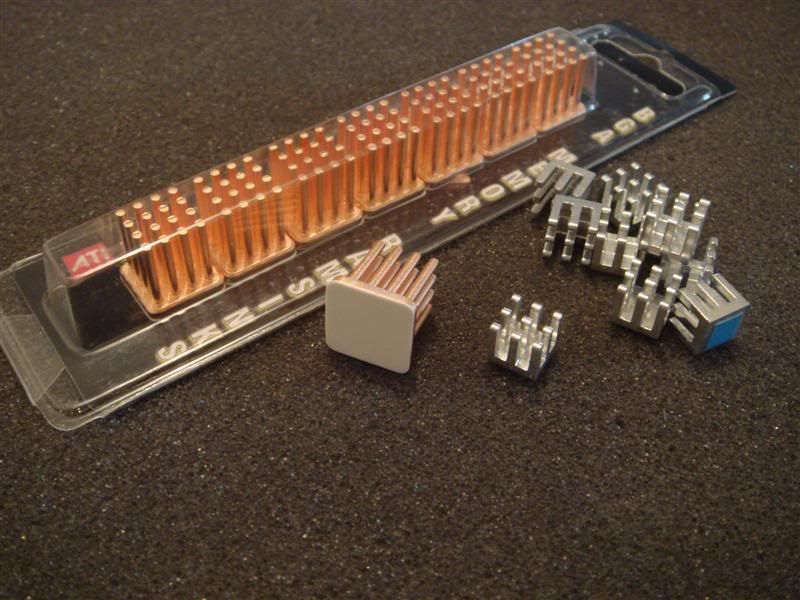
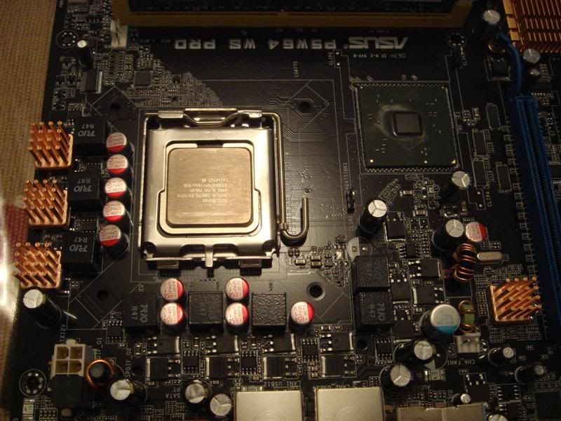
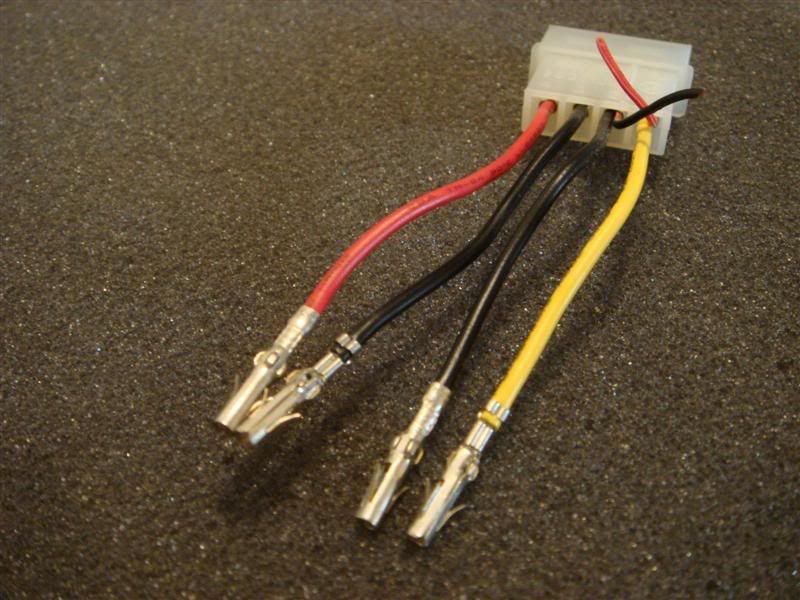
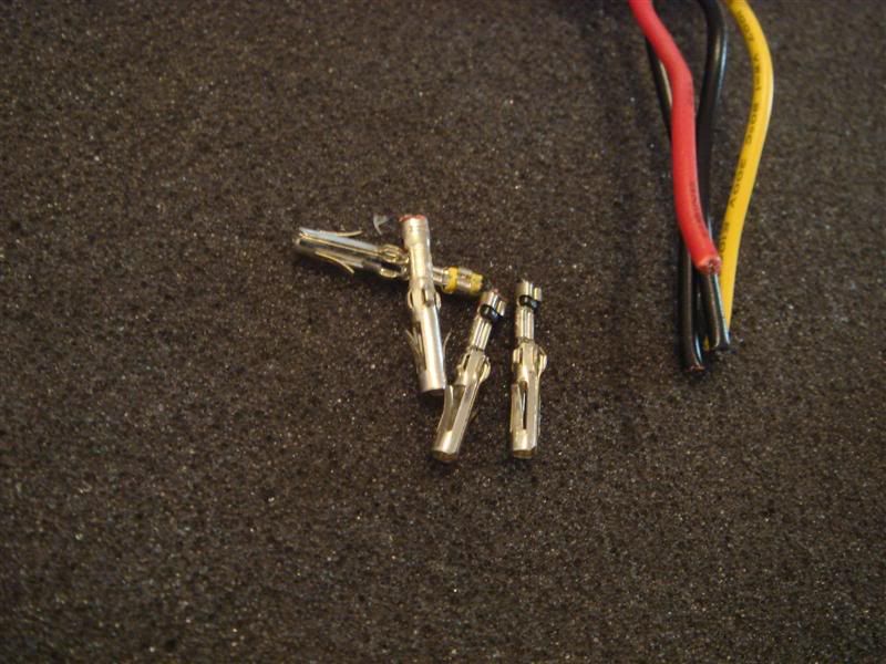
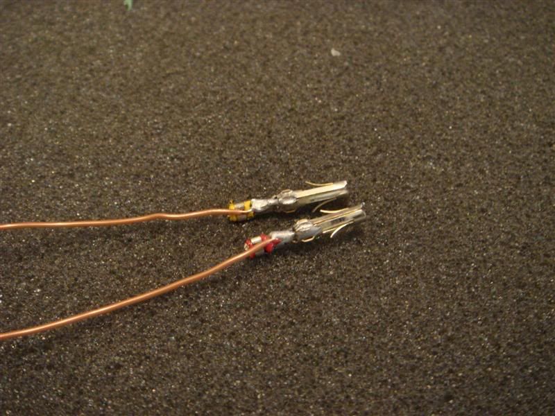
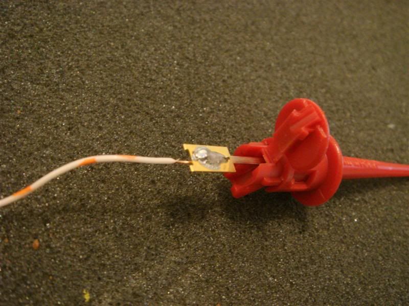
Now you have connected the wires to the grabbers. It is a good practice to keep all your mosfets running happily by cooling them down, especially when you intend to run more voltage through them. I ordered some Swiftech BGA Copper ramsinks and Microcool chipsinks for the job.
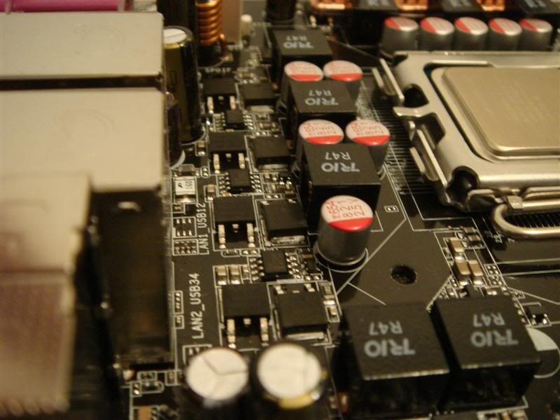
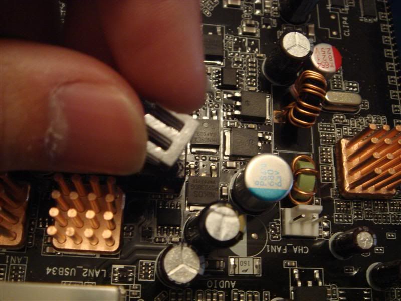
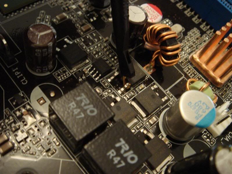
This line of mosfets is critical, and ASUS uses the lousy thick bubblegum thermal interface material:
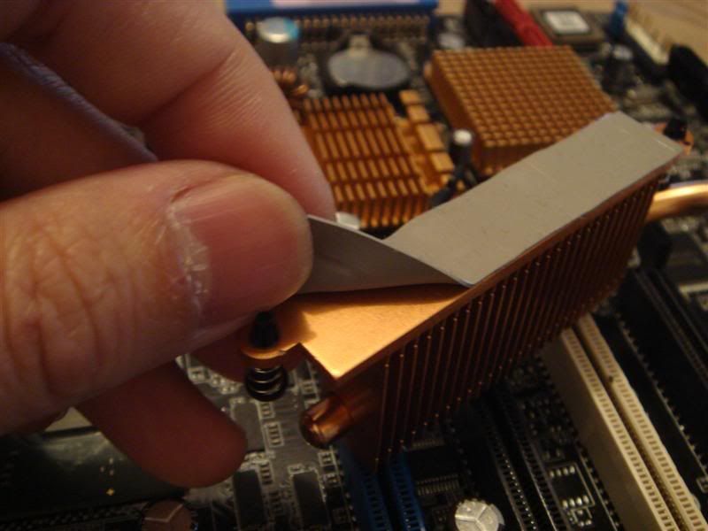
So I used the Swiftechs.
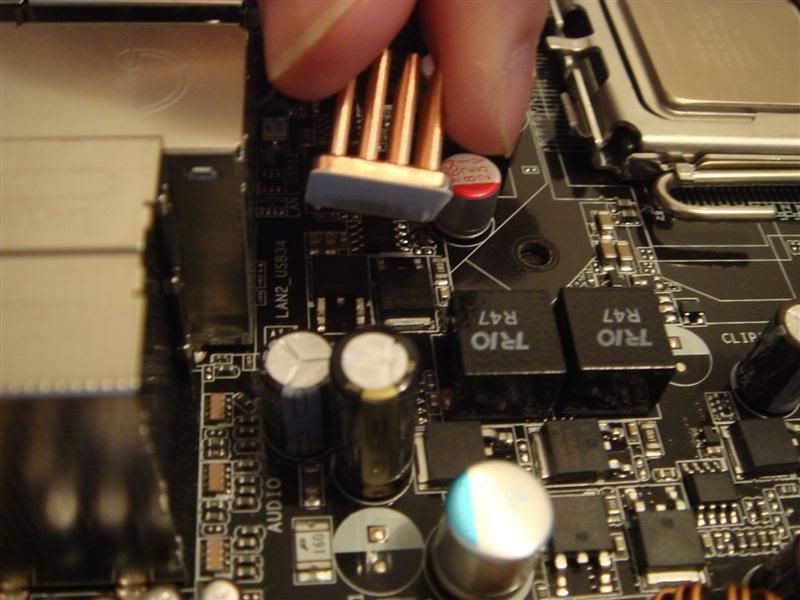
For places which are small, just put the Microcool chipsinks:
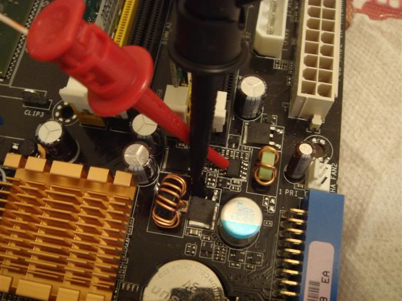
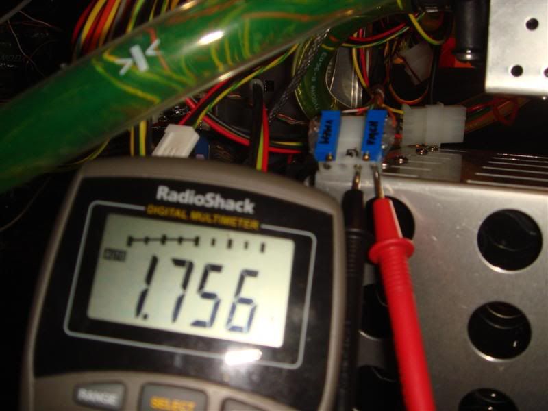
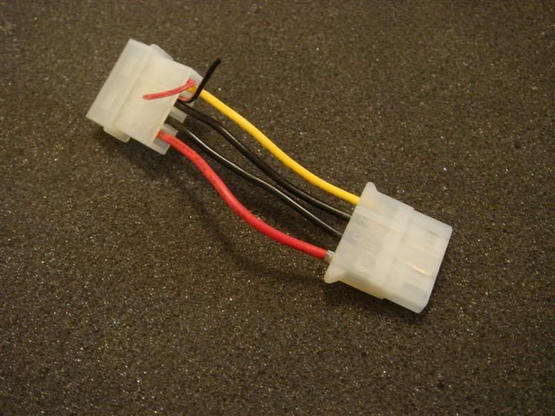
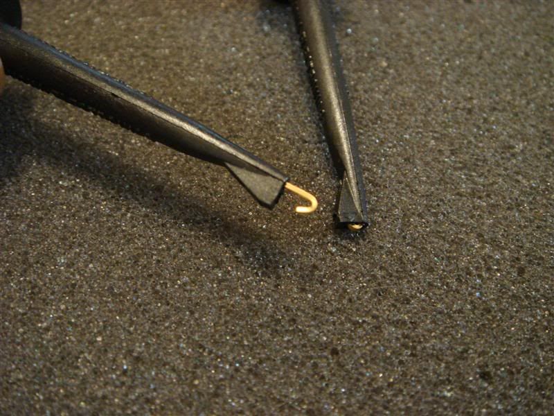
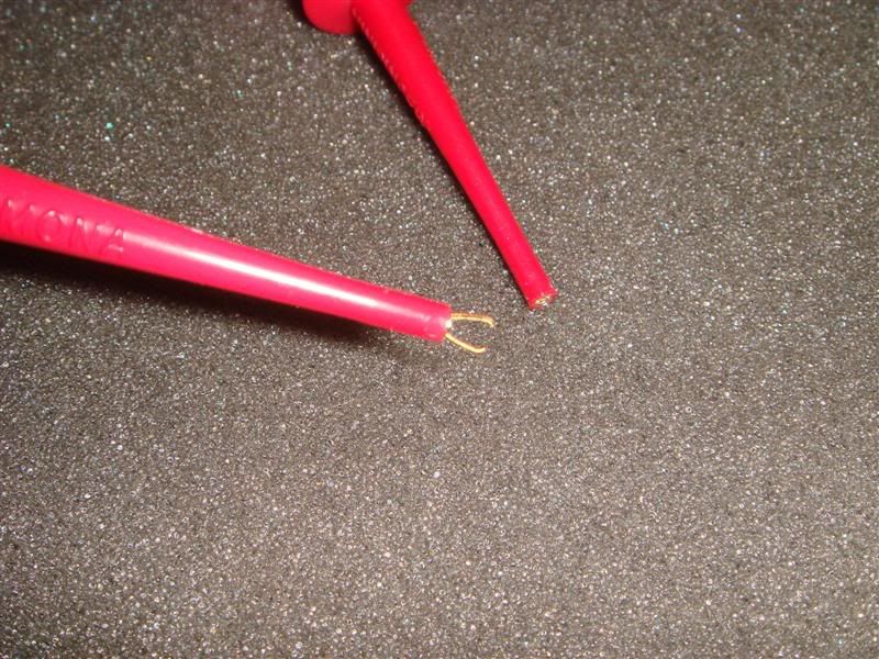
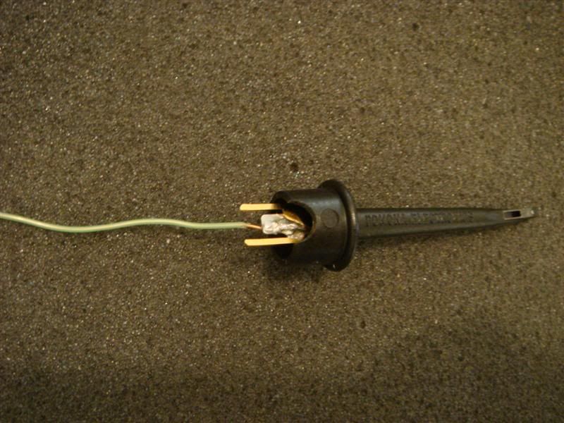
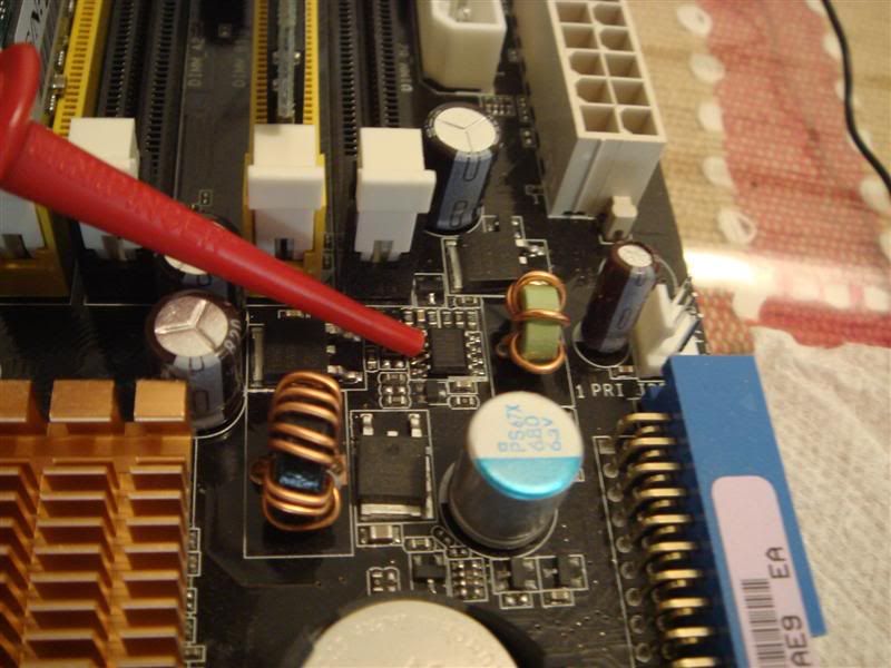
Finally, use your grabbers and pincers to hook and grab on to the points highlighted in Shamino's pics(BTW, USE THE YELLOW POINT TO READ THE VMCH VOLTAGE - THE GREEN ONE IS WRONG). Then GROUND the GREEN wire of the molex to a screw that is holding the motherboard down to the mobo:

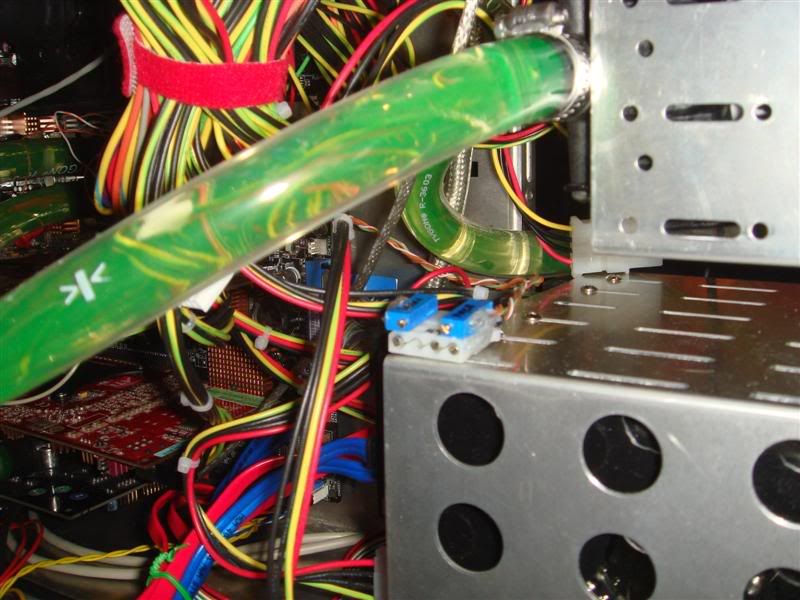
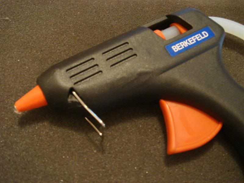
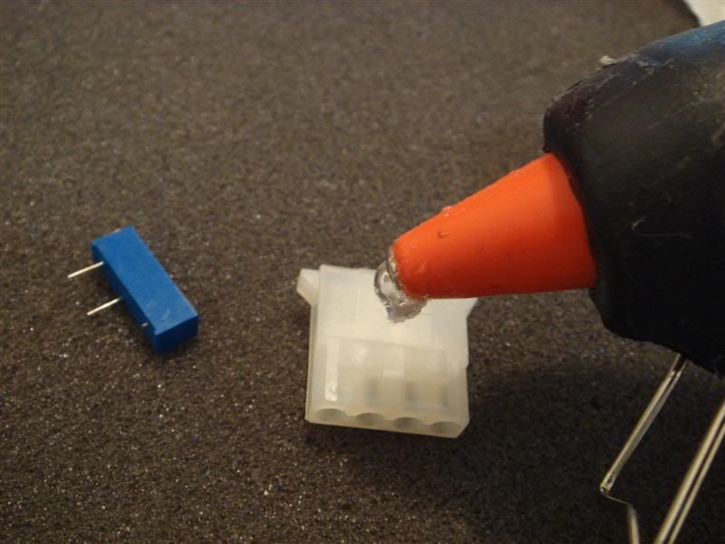
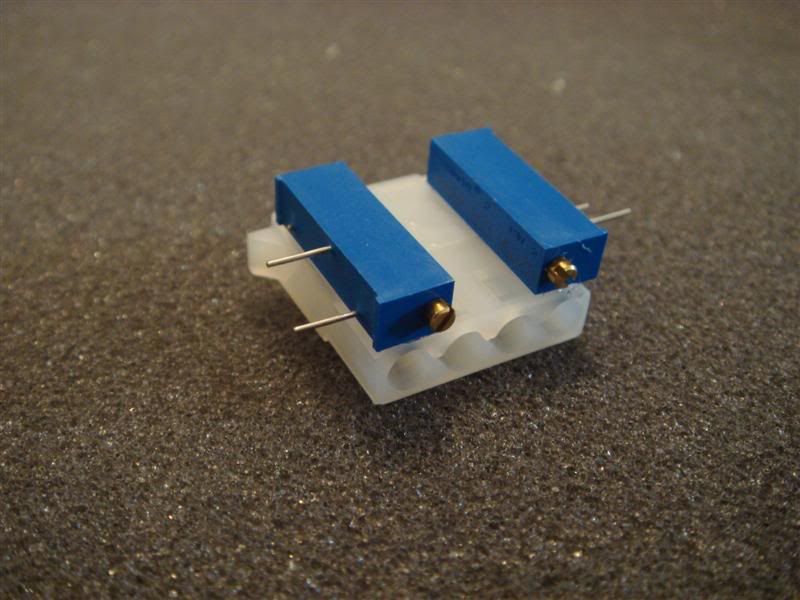
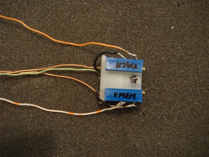
After that attach the mobo back to the case and with the hot glue gun, glue the molex to a place where you will be able to check the voltage and change the resistance to increase the voltage. This is what I did:
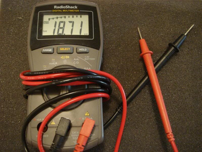
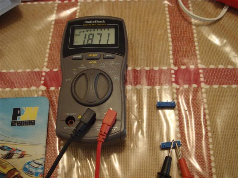
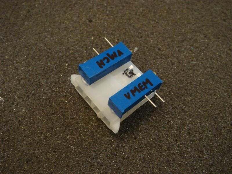
Now to see whether the voltage reading works:
VMEM
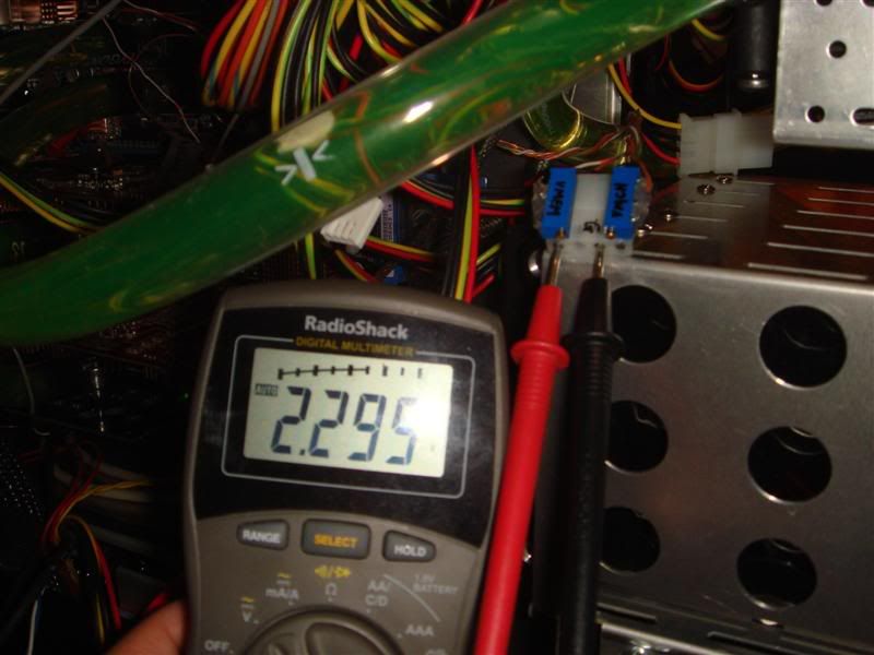
VMCH
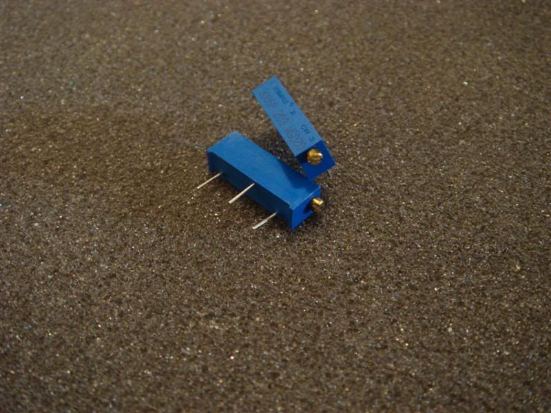
Here are some tips and safety rules before you even start turning the pots:
1. Turn the pots slowly. You don't want to turn too fast and fry something.
2. Keep the leads of the DMM plugged into the voltage reading while turning the pot, so that you know how much voltage you are actually applying while turning.
3. In the bios, please make sure you have the voltages at the LOWEST DEFAULT setting. So you know how much you are adding. Lets say you bios is set at 2.0V for VMEM and you turn the pots and now the DMM is reading 2.2V. Then you have actually added 0.2V to the bios reading. So when you are using 2.2V in the bios, the REAL voltage will be 2.5V on the DMM. Very important as people fry their DDRs when they don't remember to add the voltage added by the mod to the bios setting.

I hope I did not miss anything. Hope you guys have fun modding your mobos.

Disclaimer:
1. If you don't know what this article is talking about - please ask and don't do anything to your mobo.
2. This article is not for you if you don't know what a VMOD is.
3. I won't be responsible....bla bla bla you get the drift........
This post has been edited by kcnyc: Oct 23 2006, 04:04 PM 

 Oct 23 2006, 02:24 PM, updated 20y ago


 Quote
Quote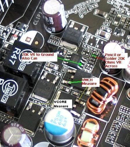

 ):
):

 ). don hurt him pls...

 really nice!!


 ]
]


 0.0211sec
 0.40
0.40
 5 queries
 GZIP Disabled