QUOTE(lucaswjk @ Jan 29 2024, 09:41 PM)
i m currently researching this...
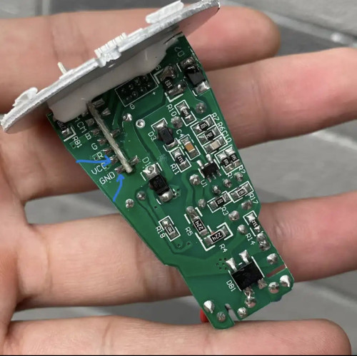
the motor1 and 2, is the power flow thru it running on 12V?
coz i know esp's gpio is only 3.3v...
can i switch it for 1second to activate the gate?
without resistor or buck converter.
On the power flow, it will be bidirectional, and the voltage can either be 12 to 24 volts or higher, depending on how the installer sets it up for you (e.g., slow or fast gate closing or opening).
You will need a resistor of about 1K ohm in series with a Ziner diode of 3.3V for each channel.
The D1 mini's GPIO can handle up to 5V without issue; just not exceeding 5V will do.
The D1 mini must be powered by a 5V power supply; anything higher will not be good.
I feel the older version of D1 Mini is more lasting than the newer version (e.g., the one without the metal shield).
QUOTE(Drian @ Jan 30 2024, 12:44 PM)
I change once a year so it is not too bad.
If you truly want long lasting like 3-4 years you could connect 2 D cell battery in series to get 3v and solder it to the terminals.
You may consider install a mini solar panel like this one (
link). I believe you will never running out of power.
It is not necessary for the solar panel to be facing up as there is not much surface area on the top part of your casing, but the side will do as your sensor consumes very little power, and a little top-up each day from the solar panel is good enough.


 Jan 24 2024, 03:26 PM
 Quote
Quote


 0.0438sec
 0.36
0.36
 7 queries
 GZIP Disabled