

 Sep 11 2011, 11:59 PM


btw, it is one of the most demanding game right now.
anyone else tried lost planet 2? dinraxx said he got very low fps in that game. it is "the way it meant to be played" game, i don't really put much hope.
Added on September 12, 2011, 12:19 amHow to mod the screen to 1080P... by AutoArc from NotebookReview.
» Click to show Spoiler - click again to hide... «
How to upgrade dv6t 61XX screen to 1080p:
Here we go. Do all the procedures defined in this document at your own risk. I will not be held responsible for any damage you do to your system from them.
There, now that's over, we can get on the the process.
1) Order the 1080p display cable from HP partsurfer. The part number is 656805-001. Then order a compatible screen like the AUO B156HW0x lines, or the LG LP156WF1.
2) Follow the dv6t service manual for more detailed directions as far as exact screw placement and such. First remove the top cover. Before that however, you need to remove the hard drive, optical drive, and keyboard. The keyboard requires that you remove the one screw from the back, then press in the hole that the
screw was in. The first time the keyboard comes out, it requires quite a bit of force to remove, but don't worry, it won't break. You are pressing on the metal frame, not the plastic. Just apply pressure slowly until the top right corner snaps out, then snap and hold the whole top edge and slide toward the display assembly. The hard drive is straichtforward, just remove the screws and gently unseat the cable and remove the drive. The optical drive is even easier. Remove the one screw and slide it out. After you have all the screws holding the top cover and speaker bar removed, disconnect the 3 ZIF connectors from the motherboard, then put your fingernail between the dark umber/silver aluminum and the plastic frame and seperate them. Start at the top and release all the latches there, then down the sides. When the top and sides are released, lift the top until the bottom comes free. Then gently remove the speaker bar above the keyboard.
3) Remove the 2 screws from the display casing and gently pry the edge between the bottom of the bezel and the LCD screen away from the screen. The latches on the bottom should release. You are supposed to release the rest of the bezel from the sreen side, not the outside, but I couldn't get that to work, so I just pried from the outside. I broke one latch, but I can't tell that it is broken. There is no wiggle in the bezel. After the latches are released, gently pull the bezel away from the screen. There is adhesive between the bezel and the metal border on the screen, so go slowly and don't break the bezel. After the adhesive is released, the bezel should lift out.
4) remove the screws holding the hinge covers on and remove the hinge covers. Just pull from where the screw was and it should come out.
5) Tilt the whole panel casing back as far as it will go. This prevents the casing from falling and putting stress on the cable. remove the 3 screws in each side of the hinge holding it to the back of the display case. Remove the 2 screws at the top of the panel holder. At this point the display case is no longer attached to the hinge ot the panel, so gently lower it to the table. Then remove the screws from each side of the panel holder to release the screen. tilt the panel forward just enough to be able to get your hand in there and release the cable. If you go too far, it will put stress on the cable. When that is released, pull the panel out.
6) At this point you can pull the old cable out and put the new one in. Pay close attention to where the cable is layed so you put the new one where it won't get pinched. You also must remove the connectors for the webcam and the HP logo on the back. The webcam connector connects just to the right of the display cable on the motherboard, and it runs up to the webcam board at the top of the display case. The HP logo cable only makes an appearance just unter where the display dable connects to the display. Be very careful placing the cable around the hinge area, if you place it wrongly it will be pinched when you screw the hinge back to the casing. Make sure the cable is seated in the channel correctly before re-screwing the hinge. I would suggest laying out the cable before actually inserting it in the channel since this will prevent you from leaving too much on one end and not enough on the other.
7) When the cable is placed correctly, put the new panel in the space and screw it in to the hinge arms. tilt the hinge forward until you can attach the new cable to the screen. When this is done, attach the webcam cable to the webcam and lift the back of the display casing up until the panel is seated in it and there are no wires being pinched. Make sure to check the WLAN wires running up the right side. Also make sure that the HP logo cable is hanging below the panel, not between it and the casing. Now re-attach the screws holding the back casing to the hinge assembly Carefully, not pinching cables. Then re-attach the HP logo cable and put the hinge covers back and screw them in. Now you can put the display bezel back and press it firmly in on all sides until it is snapped in. Then put the screws back and the rubber covers.
8) put back the speaker bar and top cover. Press the edges of the top cover straight down, do not slide them in. They will snap nicely if you push straight down. Now attach all the screws and replace the keyboard, hard drive, and optical drive. Put back all the screws holding those on and replace the service cover.
I haven't included exact motions for removing many of the parts, as you really must just play with them until they come loose. The manual says you must, but you don't have to remove the WLAN module or the system board. The manual also shows removing the display assembly from the main body, but I didn't.
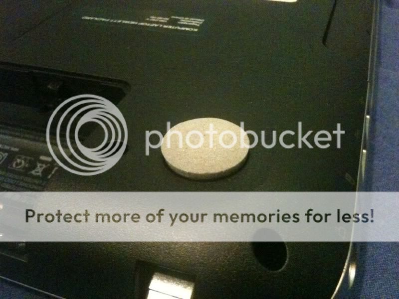
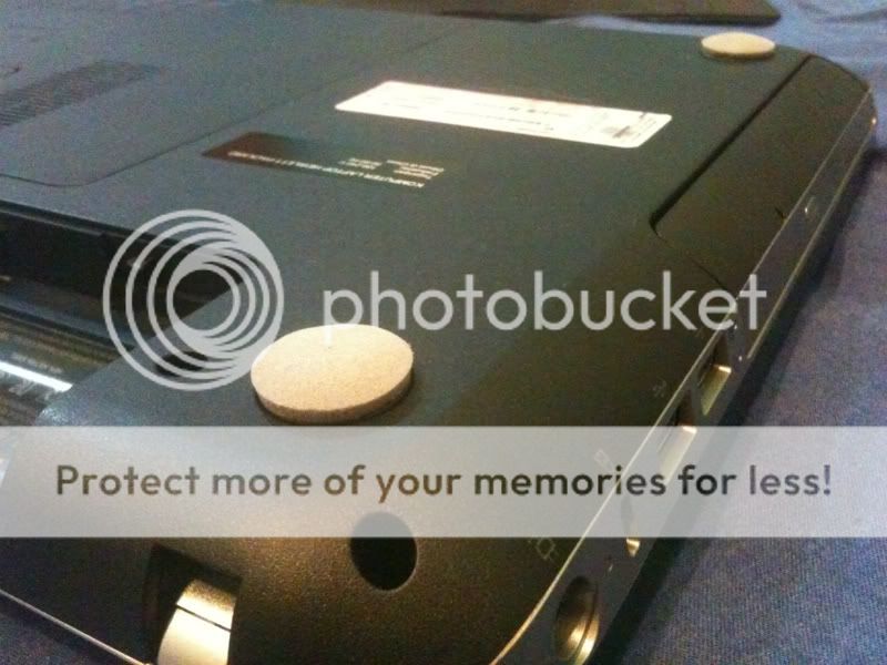
I also took some pictures of the disassembled laptop.
Here we go. Do all the procedures defined in this document at your own risk. I will not be held responsible for any damage you do to your system from them.
There, now that's over, we can get on the the process.
1) Order the 1080p display cable from HP partsurfer. The part number is 656805-001. Then order a compatible screen like the AUO B156HW0x lines, or the LG LP156WF1.
2) Follow the dv6t service manual for more detailed directions as far as exact screw placement and such. First remove the top cover. Before that however, you need to remove the hard drive, optical drive, and keyboard. The keyboard requires that you remove the one screw from the back, then press in the hole that the
screw was in. The first time the keyboard comes out, it requires quite a bit of force to remove, but don't worry, it won't break. You are pressing on the metal frame, not the plastic. Just apply pressure slowly until the top right corner snaps out, then snap and hold the whole top edge and slide toward the display assembly. The hard drive is straichtforward, just remove the screws and gently unseat the cable and remove the drive. The optical drive is even easier. Remove the one screw and slide it out. After you have all the screws holding the top cover and speaker bar removed, disconnect the 3 ZIF connectors from the motherboard, then put your fingernail between the dark umber/silver aluminum and the plastic frame and seperate them. Start at the top and release all the latches there, then down the sides. When the top and sides are released, lift the top until the bottom comes free. Then gently remove the speaker bar above the keyboard.
3) Remove the 2 screws from the display casing and gently pry the edge between the bottom of the bezel and the LCD screen away from the screen. The latches on the bottom should release. You are supposed to release the rest of the bezel from the sreen side, not the outside, but I couldn't get that to work, so I just pried from the outside. I broke one latch, but I can't tell that it is broken. There is no wiggle in the bezel. After the latches are released, gently pull the bezel away from the screen. There is adhesive between the bezel and the metal border on the screen, so go slowly and don't break the bezel. After the adhesive is released, the bezel should lift out.
4) remove the screws holding the hinge covers on and remove the hinge covers. Just pull from where the screw was and it should come out.
5) Tilt the whole panel casing back as far as it will go. This prevents the casing from falling and putting stress on the cable. remove the 3 screws in each side of the hinge holding it to the back of the display case. Remove the 2 screws at the top of the panel holder. At this point the display case is no longer attached to the hinge ot the panel, so gently lower it to the table. Then remove the screws from each side of the panel holder to release the screen. tilt the panel forward just enough to be able to get your hand in there and release the cable. If you go too far, it will put stress on the cable. When that is released, pull the panel out.
6) At this point you can pull the old cable out and put the new one in. Pay close attention to where the cable is layed so you put the new one where it won't get pinched. You also must remove the connectors for the webcam and the HP logo on the back. The webcam connector connects just to the right of the display cable on the motherboard, and it runs up to the webcam board at the top of the display case. The HP logo cable only makes an appearance just unter where the display dable connects to the display. Be very careful placing the cable around the hinge area, if you place it wrongly it will be pinched when you screw the hinge back to the casing. Make sure the cable is seated in the channel correctly before re-screwing the hinge. I would suggest laying out the cable before actually inserting it in the channel since this will prevent you from leaving too much on one end and not enough on the other.
7) When the cable is placed correctly, put the new panel in the space and screw it in to the hinge arms. tilt the hinge forward until you can attach the new cable to the screen. When this is done, attach the webcam cable to the webcam and lift the back of the display casing up until the panel is seated in it and there are no wires being pinched. Make sure to check the WLAN wires running up the right side. Also make sure that the HP logo cable is hanging below the panel, not between it and the casing. Now re-attach the screws holding the back casing to the hinge assembly Carefully, not pinching cables. Then re-attach the HP logo cable and put the hinge covers back and screw them in. Now you can put the display bezel back and press it firmly in on all sides until it is snapped in. Then put the screws back and the rubber covers.
8) put back the speaker bar and top cover. Press the edges of the top cover straight down, do not slide them in. They will snap nicely if you push straight down. Now attach all the screws and replace the keyboard, hard drive, and optical drive. Put back all the screws holding those on and replace the service cover.
I haven't included exact motions for removing many of the parts, as you really must just play with them until they come loose. The manual says you must, but you don't have to remove the WLAN module or the system board. The manual also shows removing the display assembly from the main body, but I didn't.
I also took some pictures of the disassembled laptop.
This post has been edited by Acid_RuleZz: Sep 12 2011, 12:19 AM
 Quote
Quote


 really thx alot man.

 )
)
 0.0380sec
 0.65
0.65
 6 queries
 GZIP Disabled