

 Aug 5 2010, 02:41 AM

This time around, as opposed to having all sorts of wires running through the kit, using a fairly sizable switch assembly, a big battery holder and battery assembly; I’m going small scale. Below is a list of the components I will be using for this modification:
* 3mm Red LED rated at 1.85 forward Volt at 10mA
* 150 ohm resistor
* Small reed switch
* SR521 watch batteries that put out 1.55 Volts each
* A rare earth magnet
And here is a picture of the above mentioned parts:
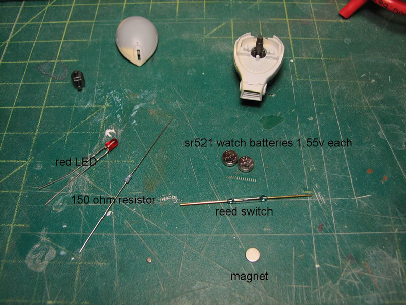
The idea here is to keep the components as small as possible so as to fit within the confines of the head assembly. The reed switch is a magnetic switch. It is basically two leads piped into a glass tube, so when placing a magnet over the leads or over the glass the leads connect and a connection is formed. It’s pretty damn cool, and these switches were about a buck a piece, so this beats the hell out of building my own magnetic switch or just using your standard mechanical switch.
The resistor is calculated out according to my power source and the LED’s specs. It’s pretty basic math: resistor ® = (Power Supply Voltage – LED’s forward Voltage)/LED’s current rating. OR you can just cheat and use an online LED calculator. So with what I have, I need to use a 150 ohm resistor. First things first, connecting all the components and just doing a quick test.
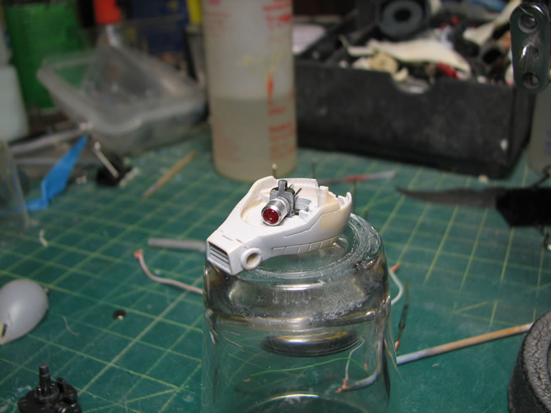
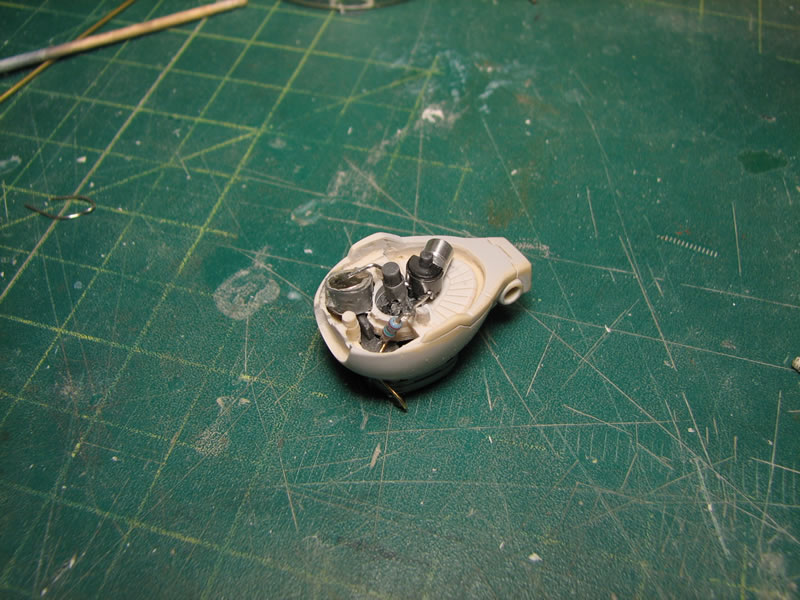
Next up is to modify the head and internals so that everything fits into place. The mono eye holder is cut and sanded, then two small holes are drilled to accommodate the LED anode and cathode. The LED assembly is test fitted, which resulted in the need to further grind down the mono eye holder. About a third of the part was sanded away. This was the only part that required significant modifications, and it was just trimming down the part by sanding it down and drilling holes.
Keeping the LED alone is kinda tacky as it’s just one long bulb; so to make it look more mono-eye like, a metal collar is added. Even with the small mono eye window, this small amount of detail is still fairly clear, and should still be visible once the mono eye lights up.
With the LED bulb in place I can now focus on the rest of the electronic components. The batteries are wrapped with duct tape and placed in series so that I get a total output of 3.1 volts. 1.55 volts in the single battery cell isn’t enough power to light up the 1.85 volt LED. The internal section of the head at the back is an open space and perfect for fitting most of the electronics. A bit of resin carving and shaving was needed to get the battery pack to fit just right and have the top half of the head come down.
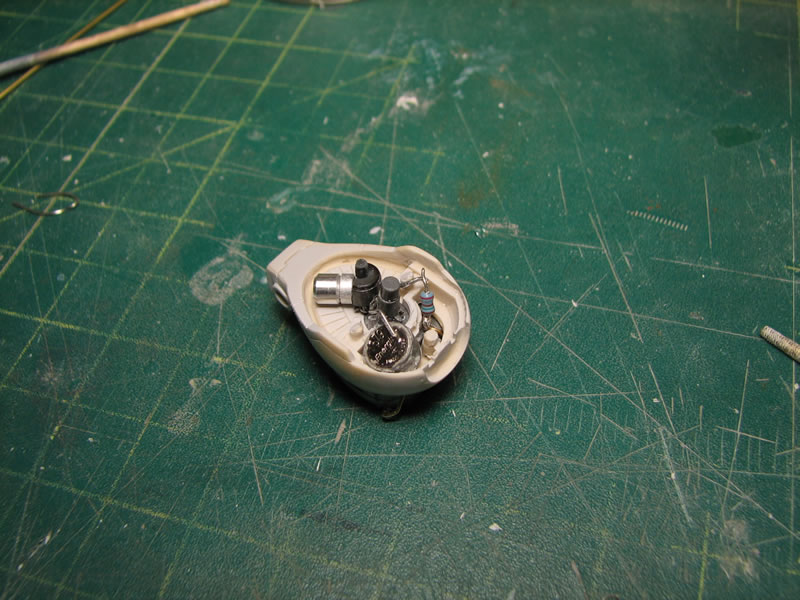
The reed switch, as small as it is, wasn’t small enough to fit inside the head assembly, so a modification to the bottom of the neck piece was needed. A concave cavity was carved out of the bottom that fit the reed switch. The leads were then carefully bent. Side note: the reed switches are fairly delicate, while I was bending my first reed switch, the glass broke causing the entire switch to come apart. The leads are positioned to run up the back of the back corners of the neck and through bottom of the head. The only issue I have is that the switch leads are exposed and run up the side of the neck, but this is an easy fix with some mesh tubing, it’ll even look like a small bit of added detailing.
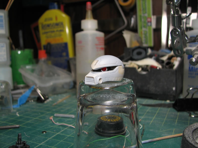
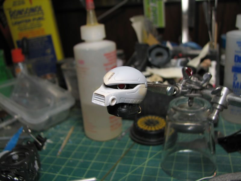
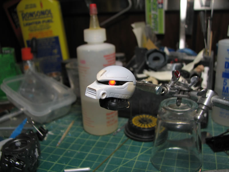
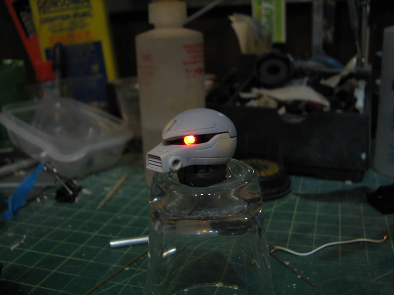
After some fiddling with the fit of all the components to get all the connections set; everything came together quite well. And placing a magnet at the bottom of the neck assembly turns on the LED. The entire assembly resides within the head and neck and operating the LED only requires placing a magnet at the bottom of the neck.

And now for the pictures of the completed assembly.
This post has been edited by VincC454: Aug 5 2010, 11:23 AM
 Quote
Quote


 0.0168sec
 1.09
1.09
 7 queries
 GZIP Disabled