

I just have and I think it sounds better. Need time to verify

Wanna ask around if anyone here has done the same.
DIY T-Amp User V2, TA2020 AIR CORES!, ~~~~~~~~~~~~~~~~~~~~~~~~~~~~
|
|
 Jun 16 2010, 10:49 PM Jun 16 2010, 10:49 PM
Return to original view | Post
#1
|
 
Senior Member
936 posts Joined: Jun 2005 |
Has anyone tried supplying an external 5V to the ta2020 ?
I just have and I think it sounds better. Need time to verify Wanna ask around if anyone here has done the same. |
|
|
|
|
|
Jun 21 2010, 12:35 PM
Return to original view | Post
#2
|
|
Senior Member
936 posts Joined: Jun 2005 |
No.
I think you get what I meant wrong. There is a 5V regulator onboard. But I think Its rather weak cos it has to supply quite a few circuits like the digital and analog processing units. What I did recently was to cut leg 30 off and use 7805 to supply 5V to pin 2 and 8. From the scope there were no more ripples to those pins. Soundwise, I don't wanna say much cos I was hoping someone else could do a similar mod to verify my results. |
|
|
Jun 21 2010, 03:22 PM
Return to original view | Post
#3
|
|
Senior Member
936 posts Joined: Jun 2005 |
The efficiency of 88% comes from the class D design. Mind you, it is supposed to be theoretically 100% efficient.
The Linear regulator is built in. It supplies power to the digital circuitry that is the integrators and the other gain and filter circuitry as well as the analog input section. In the datasheet its the op-amp on the input side and that big black box they label processing and modulation. Will upload photos a bit later but basically its just to cut off pin 30 from the pcb and solder the output of the 7805 to that hole to replace the internal 5V regulator. Preliminary tests show oscillation which is a sign of under current on pin 30. Those I got from the scope with 1khz output and 8 ohm dummy load. Only thought to try it out after some guys in diy audio made a custom board which not only supplies 5V from an external regulator but also has separate regulators for each of the power supplies. This post has been edited by sakaic: Jun 21 2010, 03:24 PM |
|
|
Jun 23 2010, 07:07 PM
Return to original view | Post
#4
|
|
Senior Member
936 posts Joined: Jun 2005 |
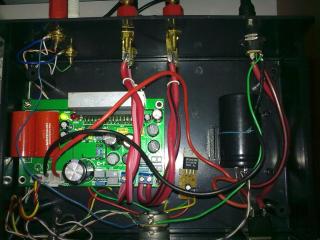
As promised, here are some photos of what Ive done so far.
The addition is half of what I want to do to the amp. 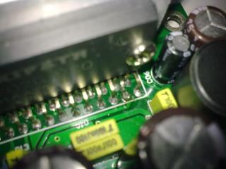

the first half is to make sure that power supplies are as clean and steady as possible. The second is to return the amp to datasheet spec. I am curious as to how it sounds as it was intended. After all all the THD and performance figures that we are given come from that config. So far I have changed the diodes at the bottom and reverted the 0.47u output cap to 0.22u as per the datasheet. Then next is to change the inductors and the 0.1u caps back to original spec. Also, building a linear power supply at 14.1V using a KA78T12 with 3 diodes at pin 2. |
|
|
Jun 23 2010, 10:07 PM
Return to original view | Post
#5
|
|
Senior Member
936 posts Joined: Jun 2005 |
Well.....there are some that I will share cos of the expected results and some that I wanted to ask ppl to verify as a double blind.
The ones I wanna share. - changing the inductors to the low noise ferrites and 15uH has opened up the sound quite a bit. The sound staging is now better. Echos I guess -changing the .47uF caps definitely made a big change. On my Usher s-520, the details were much better. Hearing new things. On the downside, there is so much of everything else that the sound might be a tad bright on some speakers like AE Neo 1 and also makes the bass less 'there' The 7805 mod I am hoping for someone to confirm the results. But I have heard much better drive. It doesn't saturate so easily any more. It still will (low power) on something fast like Viva La Vida but on something vocally strong like jazz etc. it sounds better. p.s. me currently listening to paradiso girls to destress helps in evaluating the amp. Damn burnt fingers.......... This post has been edited by sakaic: Jun 23 2010, 10:25 PM |
|
|
Jun 24 2010, 11:12 AM
Return to original view | Post
#6
|
|
Senior Member
936 posts Joined: Jun 2005 |
I think so......got them "illegally" from a friend who took some from the engineering bench
 He told me they use that on the tester as these are the type that have low noise emission. And by tester I mean IC tester |
|
|
|
|
|
Jun 24 2010, 07:50 PM
Return to original view | Post
#7
|
|
Senior Member
936 posts Joined: Jun 2005 |
The thing is that it is a digital amp.
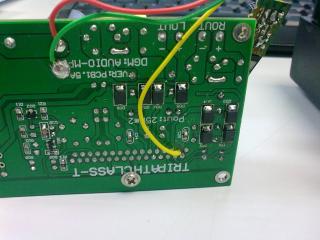
From the scope at idle with no inputs already switching at 875kHz to get the 6V each output terminal. the overshoot is about 10% I haven't scoped it yet but I hope it helps. I think the bad thing ppl always use the term class-T is that they forget it is still a class D. Just a very advanced class-D. As promised here's more or less the final mods I wanna do to the amp minus the linear power supply. 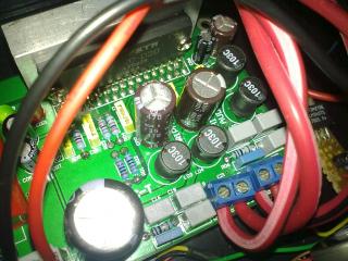
All the output caps and inductors are now datasheet spec for 8ohm speakers. It sounds VERY different now. very dynamic and detailed. Musical but maybe a tad too bright for some peoples taste. Has that tube like sound. This post has been edited by sakaic: Jun 24 2010, 08:02 PM |
|
|
Jun 25 2010, 12:13 AM
Return to original view | Post
#8
|
|
Senior Member
936 posts Joined: Jun 2005 |
kww, the cap is a 10mF. The 7805 is a bit warm but ok.
The biggest change in performance came from changing the 0.47u out to 0.22u and the inductors. Makes a lot of difference. Now I can safely say that my 2020 is almost on par vocally with my 2024. The thing is that this Helder 2020 board is poorly designed and made. The routing for the outputs are a bit weird as far as the placement of components and this causes small differences in the output offset voltage as well as very minor differences in the output (from a scope). To understand what I mean go through the datasheet regarding component placement and pcb design. BTW I think I found a potential replacement for the tripath series from Sanyo. Not yet released but in terms of architecture very similar. This post has been edited by sakaic: Jun 25 2010, 12:18 AM |
|
|
Jun 25 2010, 10:16 AM
Return to original view | Post
#9
|
|
Senior Member
936 posts Joined: Jun 2005 |
check out the 41Hz one or the DIY paradise ones. See how the layout of the output components are
This post has been edited by sakaic: Jun 25 2010, 10:18 AM |
|
|
Jun 25 2010, 01:30 PM
Return to original view | Post
#10
|
|
Senior Member
936 posts Joined: Jun 2005 |
Oh yeah....I also removed the 1uF electrolytic from the input side.
|
|
|
Jun 25 2010, 03:19 PM
Return to original view | Post
#11
|
|
Senior Member
936 posts Joined: Jun 2005 |
I think its an attempt in increasing the input capacitance
|
|
|
Jun 26 2010, 08:41 PM
Return to original view | Post
#12
|
|
Senior Member
936 posts Joined: Jun 2005 |
yes. But check the impedance of your speaker. There is different value for different impedance. I also changed the value for cdo to datasheet value.
|
|
|
Jun 27 2010, 12:06 AM
Return to original view | Post
#13
|
|
Senior Member
936 posts Joined: Jun 2005 |
QUOTE(cresstt @ Jun 26 2010, 11:56 PM) my itchy hands are contemplating to change the 2 caps on the MKIII output stage... They arent correct are they when referring to the datasheet ? Look for the one in series with a resistor and check the value. Then the other one is the one that you highlighted, the lower one is the other one i changed. the other 220n I changed to a higher grade wima (syok sendiri) refer to the datasheet then slowly trace back. Then you will see what is the same and what is different. Added on July 1, 2010, 2:00 pmThread so quiet already? was hoping for some feedback This post has been edited by sakaic: Jul 1 2010, 02:00 PM |
|
|
Jul 6 2010, 10:51 AM
Return to original view | Post
#14
|
|
Senior Member
936 posts Joined: Jun 2005 |
0.47u is correct if your speaker impedance is 4ohm
|
|
|
Jul 6 2010, 11:42 PM
Return to original view | Post
#15
|
|
Senior Member
936 posts Joined: Jun 2005 |
for the 0.22uf thats correct.
now i have a problem.......I have 2 versions of the datasheet the one you showed is from the profusionplc website. The other one I have is an earlier version hanging somewhere. the value for the super small cap is different. The profusionplc shows 0.1uF and the other one says 0.01uf. I think I will follow the profusion datasheet. Now have to change back. But the other caps are per the datasheet. there is a footnote at the bottom of the picture of the IC that states the value of the caps. Swapped. THIS is the sound I was expecting. Tighter bass.......dunno which *&#@er put that datasheet up...... The wrong version is numbered TA2020 – KL/7.1/03.05 at the corner of the page. This post has been edited by sakaic: Jul 7 2010, 12:28 AM |
| Change to: |  0.0338sec 0.0338sec
 1.86 1.86
 7 queries 7 queries
 GZIP Disabled GZIP Disabled
Time is now: 5th December 2025 - 01:10 PM |
 Quote
Quote