

QUOTE(mactreouser @ Mar 23 2023, 01:31 AM)
Hi,
How How to Check a 14v ran Power Adapter (whether it's die)?

looks like 24v for meHow How to Check a 14v ran Power Adapter (whether it's die)?
How to Check a Power Adapter (whether it's die)?
|
|
 Mar 23 2023, 09:53 AM Mar 23 2023, 09:53 AM
Return to original view | Post
#1
|
 
Junior Member
270 posts Joined: Sep 2016 From: Penang lo |
QUOTE(mactreouser @ Mar 23 2023, 01:31 AM) Hi, looks like 24v for meHow How to Check a 14v ran Power Adapter (whether it's die)? |
|
|
|
|
|
Mar 23 2023, 11:15 AM
Return to original view | Post
#2
|
|
Junior Member
270 posts Joined: Sep 2016 From: Penang lo |
QUOTE(mactreouser @ Mar 23 2023, 10:05 AM) Do you think the AC inputs connection on Board to the Pin of the Plug was wrong? AC is ok, they don't quite care.So after measuring at the output, doesn't have 24Vdc? just happen lately or since day1? For AC --> DC converter normally rectifier gg this is the typical sch (ignore the values) https://www.circuits-diy.com/wp-content/upl...m-Schematic.png  mactreouser liked this post
|
|
|
Mar 23 2023, 01:48 PM
Return to original view | Post
#3
|
|
Junior Member
270 posts Joined: Sep 2016 From: Penang lo |
QUOTE(mactreouser @ Mar 23 2023, 01:17 PM) Wow... Appreciate your helpful information! 🤩 not expert, just co-curriculum.It was working perfectly in the pass 2 weeks. And just go south yesterday 😭 I did test the 24v output via multimeter, either no value or not a stable value. So I tried on my 5v charger , it's stable at 5v+-. That means multimeter is good. You are E&E Expert! I saw an info mentioned about that this kind of power adapter mostly caused by Rectifier! But I don't really have no knowledge about that , in fact I wish to learn 🤩 Do you kind to lead me? Rectifier == 1N4007 from the picture. OptionA: If this adapter is cheap, i would suggest you buy new cause not worth the risk to play with 240V. You might cook yourself before you fix it. Just goto any hardware shop and bring your end device with you if possible to test up. If your end device is huge, just bring the adapter, they will able to find one for you. OptionB: If DIY is truly your route, from your description of <either no value or not a stable value> then yea, most likely is the rectifier, you just need to change that. Normally it is something has 4 pins --> mind to take a picture of the boards (top and bottoms)? Typically looks like this 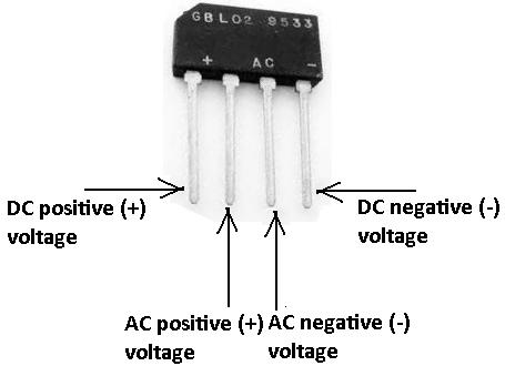 internally: 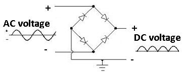 you just need to measure it (without power on) using the diode sign on your multimeter (assuming using digital)  long story short refer to this mactreouser liked this post
|
|
|
Mar 24 2023, 03:43 PM
Return to original view | Post
#4
|
|
Junior Member
270 posts Joined: Sep 2016 From: Penang lo |
QUOTE(Eventless @ Mar 23 2023, 06:02 PM) That kind of power supply design isn't used much these days. They are big, heavy and inefficient. if you look at the initial thread, you will find a transformer there and i suspect the one IC beside the heatsink is the rectifier but without proper image, i cannot confirmNearly all of the power supply these days are switch mode power supplies which are much more complicated than the design above. Some can accept a wide input voltage range(100-240v) like the one shown in the picture on the first post. https://en.wikipedia.org/wiki/Switched-mode_power_supply mactreouser liked this post
|
| Change to: |  0.0174sec 0.0174sec
 0.68 0.68
 7 queries 7 queries
 GZIP Disabled GZIP Disabled
Time is now: 26th November 2025 - 12:58 PM |
 Quote
Quote