

 Oct 26 2008, 09:14 PM
QUOTE(CV6149 @ Sep 15 2008, 06:01 PM)
littleghost,
no problem at all..ur reply is good also..
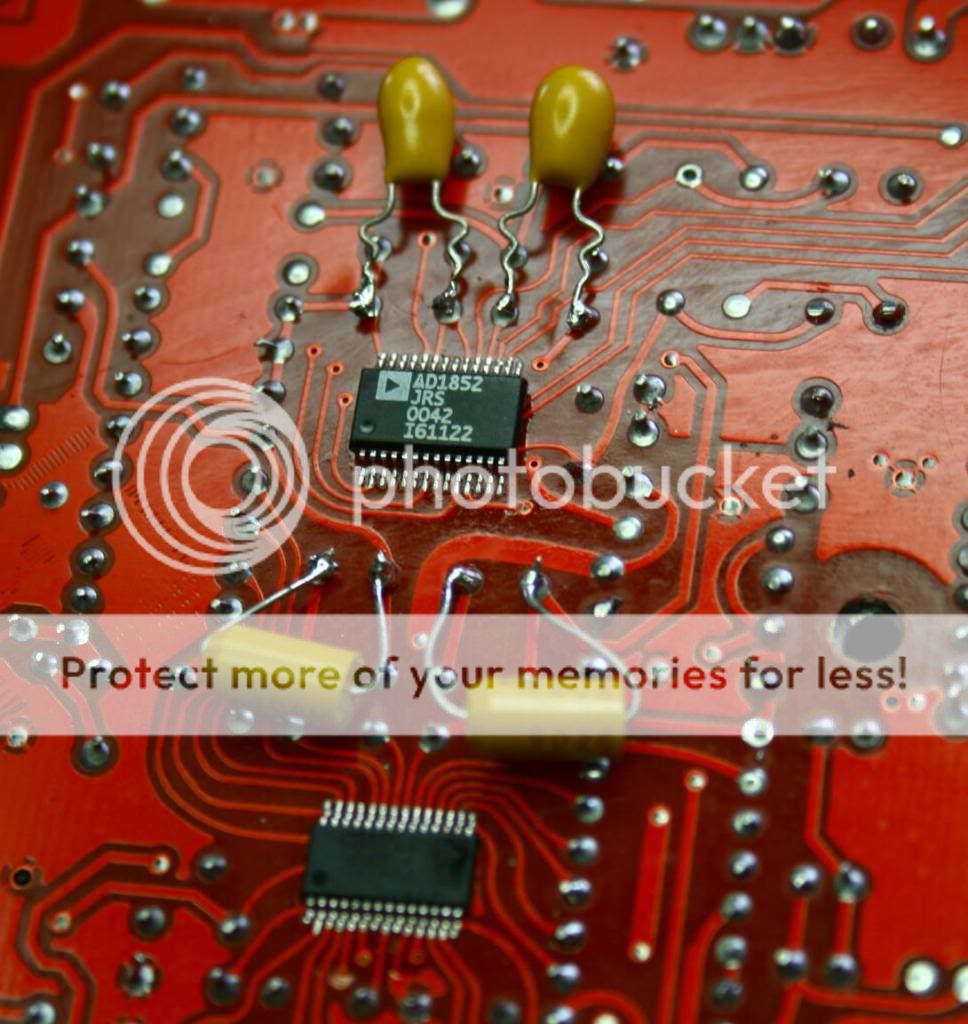
hhehhe now some comment om this mod i have done to my edifier.
Posted this in edifier thread..no response loorrr
Caps:
4700uf 25v Panasonic FCx2
100uf 25v Panasonic FM x3
22uf 25v Panasonic FC x1
0.68uf Epcos polyproplyene caps
change ne5532 to socket with OPA2134
[attachmentid=593443]

I wonder where u get those caps. I am looking for the same value like yours.no problem at all..ur reply is good also..
hhehhe now some comment om this mod i have done to my edifier.
Posted this in edifier thread..no response loorrr
Caps:
4700uf 25v Panasonic FCx2
100uf 25v Panasonic FM x3
22uf 25v Panasonic FC x1
0.68uf Epcos polyproplyene caps
change ne5532 to socket with OPA2134
[attachmentid=593443]
Added on October 26, 2008, 9:21 pm
QUOTE(LittleGhost @ Sep 15 2008, 04:06 PM)
Najmods,
One problem with your mod.
The caps should be mounted at the bottom at the PCB with shortest leads as possible. The way you're doing it wastes capacitance and adds uneccessary impedance (hence more noise). Proper bypassing mod should be done under the board or under the socket if you're good enough.
EDIT: Why am i replying to a content months ago? LOL.
Anyway nice mod bro. Personally I'm too lazy to do caps mod for my equipments.
I always see the Paper in oil PIO doing bypass for some of the power supply cap. The value is typically small like 0.033 uF doing bypass for the 330 uF power supply and even signal caps (isnt that bypass is for power supply). One problem with your mod.
The caps should be mounted at the bottom at the PCB with shortest leads as possible. The way you're doing it wastes capacitance and adds uneccessary impedance (hence more noise). Proper bypassing mod should be done under the board or under the socket if you're good enough.
EDIT: Why am i replying to a content months ago? LOL.
Anyway nice mod bro. Personally I'm too lazy to do caps mod for my equipments.
Can I know whow doesputting parallel a small cap to a big cap is a bypass?
This post has been edited by ccschua: Oct 26 2008, 09:21 PM
 Quote
Quote
 0.0240sec
 0.93
0.93
 7 queries
 GZIP Disabled