


The design, the bottom three pin on the right side of the opamp is bent:

How it looks:

Inside the DAC:

DIY HACK MOD, Everything paranormal and ™ infringement
|
|
 Apr 16 2008, 03:54 PM Apr 16 2008, 03:54 PM
|
 
Senior Member
5,211 posts Joined: Feb 2005 From: Konohana |
Behold! The world first (I think) dual to single adapter! Too lazy to buy the single version of LME49720, so I mod the socket itself to comply with single
The design, the bottom three pin on the right side of the opamp is bent:
How it looks:
Inside the DAC:
|
|
|
|
|
|
Apr 26 2008, 09:57 AM
|

Senior Member
571 posts Joined: Aug 2005 From: 221B Baker Street |
wow wanna ask where u guys buy those Elna Cerafine cap and MUSE ... bcoz here selling not complete value that diyparadise selling mine to share .... tq tq
 |
|
|
Jul 13 2008, 09:43 PM
|
|
Senior Member
5,211 posts Joined: Feb 2005 From: Konohana |
My new mods, single dual to dual single opamp
I solder it down to the socket to make it more secure, plus I put 20nF as a bypass on positive and negative rail to clear up white noise (as I read). Other mod that I done to this DAC is replaced all capacitor on digital circuit with Sanyo OS-CON 100uFx2 per hole (stock is 180uF) plus I change decoupling caps with 0.47uF Philips MKT (on the back of the though, its too big) |
|
|
Jul 13 2008, 09:58 PM
|

Senior Member
8,046 posts Joined: Jan 2003 |
Goodness me?... your soldering?... could you do better and for goodness sake you could make use of solid core copper wires taken from Astro coaxial cable. Use your flat pliers to make straight links out of the coax. It'll look a lot neater.
|
|
|
Jul 13 2008, 10:04 PM
|
|
Senior Member
5,211 posts Joined: Feb 2005 From: Konohana |
QUOTE(bsl555 @ Jul 13 2008, 09:58 PM) Goodness me?... your soldering?... could you do better and for goodness sake you could make use of solid core copper wires taken from Astro coaxial cable. Use your flat pliers to make straight links out of the coax. It'll look a lot neater. Sorry, I lack of equipment, I just use anything that I have and what can I find, which is just my hand .....and a solder iron   This post has been edited by Najmods: Jul 13 2008, 10:05 PM |
|
|
Jul 13 2008, 10:09 PM
|
|
Senior Member
8,046 posts Joined: Jan 2003 |
QUOTE(Najmods @ Jul 13 2008, 10:04 PM) Sorry, I lack of equipment, I just use anything that I have and what can I find, which is just my hand .....and a solder iron Oh well, allow me to advise you that its all delicate inside there and hope you don't do like that all the time where damage to the PCB can be irreversible...more damage than good. Buy a soldering iron with different bits and make use of some solder flux to obtain a better soldering point. Practice makes perfect. Good luck man!. P.S. Truthfully I hate sockets and socketed chips. They just attract more noise. This post has been edited by bsl555: Jul 13 2008, 10:10 PM |
|
|
|
|
|
Jul 13 2008, 10:13 PM
|

Senior Member
8,186 posts Joined: May 2005 From: Beaumont, Baile Ath Cliath, EIRE. |
Good advice bsl!
 pay attention, 'grasshopper'. (can't resist it!)  |
|
|
Jul 13 2008, 10:20 PM
|
|
Senior Member
8,046 posts Joined: Jan 2003 |
QUOTE(jazzy939 @ Jul 13 2008, 10:13 PM) Good advice bsl! Yes!.. nuture somebody into a real "modder" not "hacker"!. pay attention, 'grasshopper'. (can't resist it!)  |
|
|
Jul 13 2008, 10:43 PM
|
|
Senior Member
5,211 posts Joined: Feb 2005 From: Konohana |
QUOTE(bsl555 @ Jul 13 2008, 10:09 PM) Oh well, allow me to advise you that its all delicate inside there and hope you don't do like that all the time where damage to the PCB can be irreversible...more damage than good. Buy a soldering iron with different bits and make use of some solder flux to obtain a better soldering point. Practice makes perfect. Good luck man!. Thanks for your advice P.S. Truthfully I hate sockets and socketed chips. They just attract more noise.  I have still much to learn, I shouldn't mod in the first place, as I have been known to be impatience plus I have shaky hands. But well, my will is stronger than all of the limitation I have still much to learn, I shouldn't mod in the first place, as I have been known to be impatience plus I have shaky hands. But well, my will is stronger than all of the limitation I'll buy the single version of it (LME49710) and solder them directly to the board without any sockets |
|
|
Jul 14 2008, 10:59 AM
|

Senior Member
3,448 posts Joined: Jan 2003 From: Sarawak |
Socket mmng intro noise, but offers flexibility and its like big PLUS PLUS to the ppl here apparently, they like trying out different opamps. What uncle BSL said was to do proper P2P wiring, but in his case, dun think the solid core of coaxial cable a good choice, no? its too big, maybe a good single core wire stripped might be okay, or leftover lead of resistors?
As uncle BSL said, practice makes perfect, proper tools help perfections and sum ppl might not agree, but to me, quality of equipment is really a big plus. Nice to see another fella taking a liking to making things to their liking. |
|
|
Sep 15 2008, 03:46 PM
|
|
Senior Member
571 posts Joined: Aug 2005 From: 221B Baker Street |
My Marantz CD5001 CDP mod still not complete yet not enuf parts ....
 My speaker passive crossover mod now waiting to buy for the LPF coil bcoz need to measure the mh value  This post has been edited by abel: Sep 15 2008, 04:00 PM |
|
|
Sep 15 2008, 04:06 PM
|

Senior Member
4,234 posts Joined: Nov 2004 |
Najmods,
One problem with your mod. The caps should be mounted at the bottom at the PCB with shortest leads as possible. The way you're doing it wastes capacitance and adds uneccessary impedance (hence more noise). Proper bypassing mod should be done under the board or under the socket if you're good enough. EDIT: Why am i replying to a content months ago? LOL. Anyway nice mod bro. Personally I'm too lazy to do caps mod for my equipments. This post has been edited by LittleGhost: Sep 15 2008, 04:08 PM |
|
|
Sep 15 2008, 06:01 PM
|

Senior Member
1,347 posts Joined: Jan 2003 |
littleghost,
no problem at all..ur reply is good also.. hhehhe now some comment om this mod i have done to my edifier. Posted this in edifier thread..no response loorrr Too bore while fasting...sleep too much also........what i did?? hehehhe mod my beloved Edifier E3100 Here is some info regarding mod i have done to my Edifier E3100.cheap stuff..but? Unbelieveable! Caps: 4700uf 25v Panasonic FCx2 100uf 25v Panasonic FM x3 22uf 25v Panasonic FC x1 0.68uf Epcos polyproplyene caps change ne5532 to socket with OPA2134 some extra padded sponge for extra deepness.hehehhe but i hate the burn in period aiihhh......... Emmm ..........what will happen if i change all that 5% ceramic resistor to metal resistor..emmm wait till im bored againlah......... **stay tune..some opamp rolling... opamp testing now is TLE2082..fuhhh!!  This speaker couple with modded AV-710..... 
This post has been edited by CV6149: Sep 15 2008, 07:45 PM |
|
|
|
|
|
Sep 15 2008, 06:35 PM
|
|
Senior Member
5,211 posts Joined: Feb 2005 From: Konohana |
QUOTE(LittleGhost @ Sep 15 2008, 04:06 PM) Najmods, Thanks for the advice, bro One problem with your mod. The caps should be mounted at the bottom at the PCB with shortest leads as possible. The way you're doing it wastes capacitance and adds uneccessary impedance (hence more noise). Proper bypassing mod should be done under the board or under the socket if you're good enough. EDIT: Why am i replying to a content months ago? LOL. Anyway nice mod bro. Personally I'm too lazy to do caps mod for my equipments. Yeah this thread is old and not many hits, but that is still a good adviceMany has happened since I last done that, I soldered the opamp directly to the socket, and I only uses one opamp per channel to reduce the 'brightness' of LME49720 This post has been edited by Najmods: Oct 26 2008, 01:55 AM |
|
|
Oct 26 2008, 01:57 AM
|
|
Senior Member
5,211 posts Joined: Feb 2005 From: Konohana |
I get a couple LT1363 (single version of LT1364) from Linear themself to try on my DAC. Installed it side by side with LME49720 (not pictured, I singled them and soldered it on the back of the PCB and bias to class A, its quite messy I don't want to show it
)Anything else, I have changed the cheap coaxial cable with a good thick one my father bought at JP, 2 meter long, soldered them directly from DAC to soundcard, before this I use RCA jack and cheap coax cable. Plus, I bypass the output caps properly now, it looks a lot better and soldered the RCA jack on the PCB itself, I want to reduce as much link as possible Any improvement? Yes, and hell a lot of it, I don't know where to start. With direct coax cable from the DAC to soundcard and direct RCA soldered on PCB, the blurry background detail is now very sharp and precise. When I soldered the LME49720 directly, it sounded a lot better, but with LT1363 accompany it (stock is Texas Instruments NE5534), it totally surprised me, its hair raising moments! The vocal locks tight in the middle, with very nice airy sound on the percussion, the guitar sounds fantastic I loved it, its less fatiguing when listening to long hours. I listening to my favorite singer, Marit Larsen now, its like a totally new experience, having vocal on its own layer, its just fantastic (eargasm ) A bit dusty, because I don't put the lid on |
|
|
Oct 26 2008, 12:37 PM
|
|
Senior Member
8,046 posts Joined: Jan 2003 |
Whenever you replace NE553x or those jellybean NJM4558,2068,2114 with something better from NS or BB, you can be damn sure to hear a significant improvement. I can never accept any of those jellybeans in any of my hardware that deploy them.
|
|
|
Oct 26 2008, 08:56 PM
|

Junior Member
108 posts Joined: Mar 2007 |
My last Aikido project...
Complete parts before connected...  Some combination in the components...  Well, the potentiometer and the output caps for driving my 32 Ohm Grado headphone...  Project on testing... 6N1P+6N6P and 5U4C rectifier...  The 6N6P... Russian, high power tube...  The DIY "monster" transformer... 300V-CT-300V/100mA (B+), 5V-CT-5V/3A (filament), 5V/3A (rectifier)... Completely oversized wire... the 3A rating is minimum, should be ok to be pushed into 5A (no voltage drop so far), still around 5.1-5.4VAC tested on 3A load...  Another shot from another side...  Rectifier changed to 5U3C/5U4GB... Even better sound...  This post has been edited by xneakers: Oct 26 2008, 08:59 PM |
|
|
Oct 26 2008, 09:14 PM
|
|
Senior Member
1,630 posts Joined: Jun 2006 |
QUOTE(CV6149 @ Sep 15 2008, 06:01 PM) littleghost, I wonder where u get those caps. I am looking for the same value like yours.no problem at all..ur reply is good also.. hhehhe now some comment om this mod i have done to my edifier. Posted this in edifier thread..no response loorrr Caps: 4700uf 25v Panasonic FCx2 100uf 25v Panasonic FM x3 22uf 25v Panasonic FC x1 0.68uf Epcos polyproplyene caps change ne5532 to socket with OPA2134
Added on October 26, 2008, 9:21 pm QUOTE(LittleGhost @ Sep 15 2008, 04:06 PM) Najmods, I always see the Paper in oil PIO doing bypass for some of the power supply cap. The value is typically small like 0.033 uF doing bypass for the 330 uF power supply and even signal caps (isnt that bypass is for power supply). One problem with your mod. The caps should be mounted at the bottom at the PCB with shortest leads as possible. The way you're doing it wastes capacitance and adds uneccessary impedance (hence more noise). Proper bypassing mod should be done under the board or under the socket if you're good enough. EDIT: Why am i replying to a content months ago? LOL. Anyway nice mod bro. Personally I'm too lazy to do caps mod for my equipments. Can I know whow doesputting parallel a small cap to a big cap is a bypass? This post has been edited by ccschua: Oct 26 2008, 09:21 PM |
|
|
Oct 26 2008, 11:13 PM
|
|
Senior Member
4,234 posts Joined: Nov 2004 |
paralleling small cap to big cap isnt really a bypass. That's a failed bypass imo.
Bypassing should be done CLOSE to the circuit, NEXT to the pins. This is to get low impedance for high frequencies as much as possible while avoiding lead inductance and noise pickup. Bypassing is also done for signals in the signal path because electrolytics simply arent low enough impedance for higher frequencies. EDIT: Bypassing for power supply is better known as decoupling. This post has been edited by LittleGhost: Oct 26 2008, 11:14 PM |
|
|
Oct 27 2008, 10:46 PM
|
|
Senior Member
1,630 posts Joined: Jun 2006 |
QUOTE(LittleGhost @ Oct 26 2008, 11:13 PM) paralleling small cap to big cap isnt really a bypass. That's a failed bypass imo. "paralleling small cap to big cap isnt really a bypass. That's a failed bypass imo. " Bypassing should be done CLOSE to the circuit, NEXT to the pins. This is to get low impedance for high frequencies as much as possible while avoiding lead inductance and noise pickup. Bypassing is also done for signals in the signal path because electrolytics simply arent low enough impedance for higher frequencies. EDIT: Bypassing for power supply is better known as decoupling. I am confused with this state ment over "Bypassing is also done for signals in the signal path because electrolytics simply arent low enough impedance for higher frequencies. " I see a lot of bypass for power supply cap. These bypass cap is soldered underside of the PCB in parallel. For example I see this 4 units of OSCON 16V 100uF giving power supply to a DAC and receiver chip.  At the bottom of the PCB, the tantalum is added. 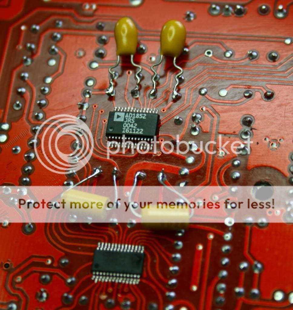 Can I know what cap is used for bypass, MICA or tantalum or film cap ? I seem to see a mixture, but not sure of which give wht sound. if bypass what is the value? is it by trial and listen or just take 1/1000 of it. If bypass for signal, is it true that Paper in oil give more warm. Please dont mind me asking, I am just a noob to diy. This post has been edited by ccschua: Oct 28 2008, 12:45 AM |
| Change to: |  0.0262sec 0.0262sec
 0.33 0.33
 6 queries 6 queries
 GZIP Disabled GZIP Disabled
Time is now: 2nd December 2025 - 11:40 AM |
 Quote
Quote