

According to the picture, it says to reduce vdroop is to shade the rfb to make resistance lower, so i need to shade the green labels only
or both yellow and green de? Thx all.
Attached thumbnail(s)
P5K SE vDroop Pencil Mod, nid guide
|
|
 Jan 18 2008, 11:07 PM, updated 18y ago Jan 18 2008, 11:07 PM, updated 18y ago
Show posts by this member only | Post
#1
|

Newbie
3 posts Joined: Jan 2008 |
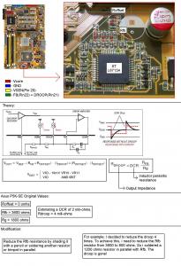
Hi all, i'm new and noob, so ar need confirmation from sifus and pros about the vdroop pencil shading mod.
According to the picture, it says to reduce vdroop is to shade the rfb to make resistance lower, so i need to shade the green labels only or both yellow and green de? Thx all. Attached thumbnail(s)
|
|
|
|
|
|
Jan 18 2008, 11:16 PM
Show posts by this member only | Post
#2
|

Junior Member
160 posts Joined: Sep 2007 |
Hello and welcome
 I am unable to help you but for a n00b you know a lot at least compare to me  Where did you get this stuff from and what it is suppose to achieve?  Sorry to annoy people around with my questions but it is nice to some times receive an answers  Tonton |
|
|
Jan 19 2008, 01:25 AM
Show posts by this member only | Post
#3
|

Senior Member
3,175 posts Joined: May 2006 |
@t00tkia
welcome to to LYN forums, please read the stickys and adhere to board rules at all times. And no, smoking pot while spamming in threads other then kopitiam will not be tolerated LoL. And have fun. only shade the RFB smd capacitor, and then use a cellotape to make sure the graphite does not get blown off. I would assume you do know the risks involved for eliminating vdroop right? if not please read below. @Nocrimes vdroop modding is to eliminate the need to set a higher voltage in bios. in normally benefits ocers. Introduction In engineering, a minimum tolerance to faults and defects has to be put into consideration for any design or product to compensate for faults or manufacturing uncertainties and design margins create a situation in which products never meet validation criteria. If the tolerance margin is set to far apart, the device or product might suffer from performance penalties or reliability issues. Intel Specification for vdroop 

These represents the droop as according to intel's specifications. The droop is to compensate for the capacitor and mosfets feeding the vcc (cpu voltage) an allowable tolerance to faults and for the capacitor charge up and discharge time. Bottemline: vdroop is to allow the power regulators and mosfets of the motherboard feeding the cpu power enough tolerance so that it does not zaps your cpu with voltage spikes and to prolong the life of the mosfets. Capacitors and mosfets as well as chokes, requires time to charge up the current needed by the cpu. and that is fine for idle to load transitions. But during load to idle transitions, the current (A) required by the cpu is suddenly stopped, but before the capacitors are allowed to discharge through heat, the voltage supplied is spiked to the cpu, as well as damaging the mosfets due to the feedback. how much is the spike to the cpu when there is 0% droop? that depends on the power phase amount supplying the cpu power as well as the load on the cpu during the load to idle transitions. So if you love your cpu, dont give them 0 vdroop under load, because they hate little spikes of 1.7v to the core  References: Intel Corp. Doc. Number: 313214-002 (November 2006) http://download.intel.com/design/processor...ts/31321402.pdf STMicroelectronics L6713A 2/3 Phase controller with embedded drivers for Intel VR10, VR11 and AMD 6 bit CPUs (07-Nov-2006) Asus P5k SE controller http://www.st.com/stonline/products/litera...2144/l6713a.pdf I will edit this when i feel more diligent to type  This post has been edited by bryanyeo87: Jan 19 2008, 01:31 AM |
|
|
Jan 19 2008, 08:44 AM
Show posts by this member only | Post
#4
|
|
Junior Member
160 posts Joined: Sep 2007 |
Thank You bryan
It seems that it is not for me as I am not into OCing, but never the less it is very interesting to know this kind of things  The reason I do not wish to Step into OCing is simple, ought I may me wrong , I Think that OC reduces The Hardware Lifespan & To be done properly it cost a bomb  Tonton |
|
|
Jan 19 2008, 03:55 PM
Show posts by this member only | Post
#5
|
|
Senior Member
3,175 posts Joined: May 2006 |
QUOTE(Nocrimes @ Jan 19 2008, 08:44 AM) Thank You bryan Ocing does in fact reduce the lifespan of the components involved, BUT, it does so less if it is done properly, because processors and chips have a good lifespan of up to 12 years(or more lol) but im pretty sure you wouldnt wanna keep the pc at that time, so you trade off 3 or 4 years for a higher performing pc. Last time during the intel prescott era, cooling would cost a bomb mainly because those little chips are nuclear generators. It seems that it is not for me as I am not into OCing, but never the less it is very interesting to know this kind of things The reason I do not wish to Step into OCing is simple, ought I may me wrong , I Think that OC reduces The Hardware Lifespan & To be done properly it cost a bomb Tonton  Consider ocing is like tuning a honda civic to produce 400bhp, its like modifying the engine, and drivetrain to give better performance at the trade off of engine lifespan. |
|
|
Jan 19 2008, 05:24 PM
Show posts by this member only | Post
#6
|
|
Newbie
3 posts Joined: Jan 2008 |
@bryan
Wah , hehe thx for the infos, very nice le. @nocrimes I found it when googling I shade the rfb smc liao, and then my vcore increased by 0.01v during idle. But donoe y when load , drops about 0.03v,(before the mod the vdroop is like 0.05+), i tink is supposed to be like tat... This post has been edited by t00tkia: Jan 19 2008, 05:25 PM |
|
|
|
|
|
Jan 19 2008, 07:10 PM
Show posts by this member only | Post
#7
|
|
Senior Member
3,175 posts Joined: May 2006 |
yea that is correct, it reduces the vdroop, if u want less vdroop, shade even more, but i would strongly suggest not to go more then that if you value both the processor and board's mosfets lifespan. and what did you use to measure the current cpu voltage?
btw, what is the voltage set at bios, idle and load. before and after the mod? |
|
|
Jan 19 2008, 07:34 PM
Show posts by this member only | Post
#8
|
|
Newbie
3 posts Joined: Jan 2008 |
I use asus pcprobe2 to measure de.
Bios setting vcore 1.33v, when idle is 1.34v, load is 1.31v running orthos. Then i tried OC to 3.2Ghz, the vcore i put 1.4v at bios, but then idle is 1.37v, load running orthos drops to 1.34v.  shoud i shade even more? shoud i shade even more? p5k se vdroop quite mafan, looks like my board cant OC well le ---EDIT-- Kk, finally done it.. running orthos at stock vcore 1.33v no drop, idle vcore is 1.34v 0.o. Thx bryan for tips This post has been edited by t00tkia: Jan 20 2008, 04:30 PM |
|
|
Jan 19 2008, 08:36 PM
Show posts by this member only | Post
#9
|
|
Senior Member
3,175 posts Joined: May 2006 |
you didnt shade it correctly, grab a multimeter and probe the resistance and reduce as per the guide
and using software to check voltage is about as accurate as driving blindfolded  |
| Change to: |  0.0169sec 0.0169sec
 1.48 1.48
 6 queries 6 queries
 GZIP Disabled GZIP Disabled
Time is now: 24th December 2025 - 03:37 PM |
 Quote
Quote